Self-Test D-1.6 Sizing Single-Storey Vents
Complete Self-Test D-1.6 and check your answers.
- Using Figure 2P-7, fill in Table 1 by identifying and sizing the wet vent installation as per the NPC.
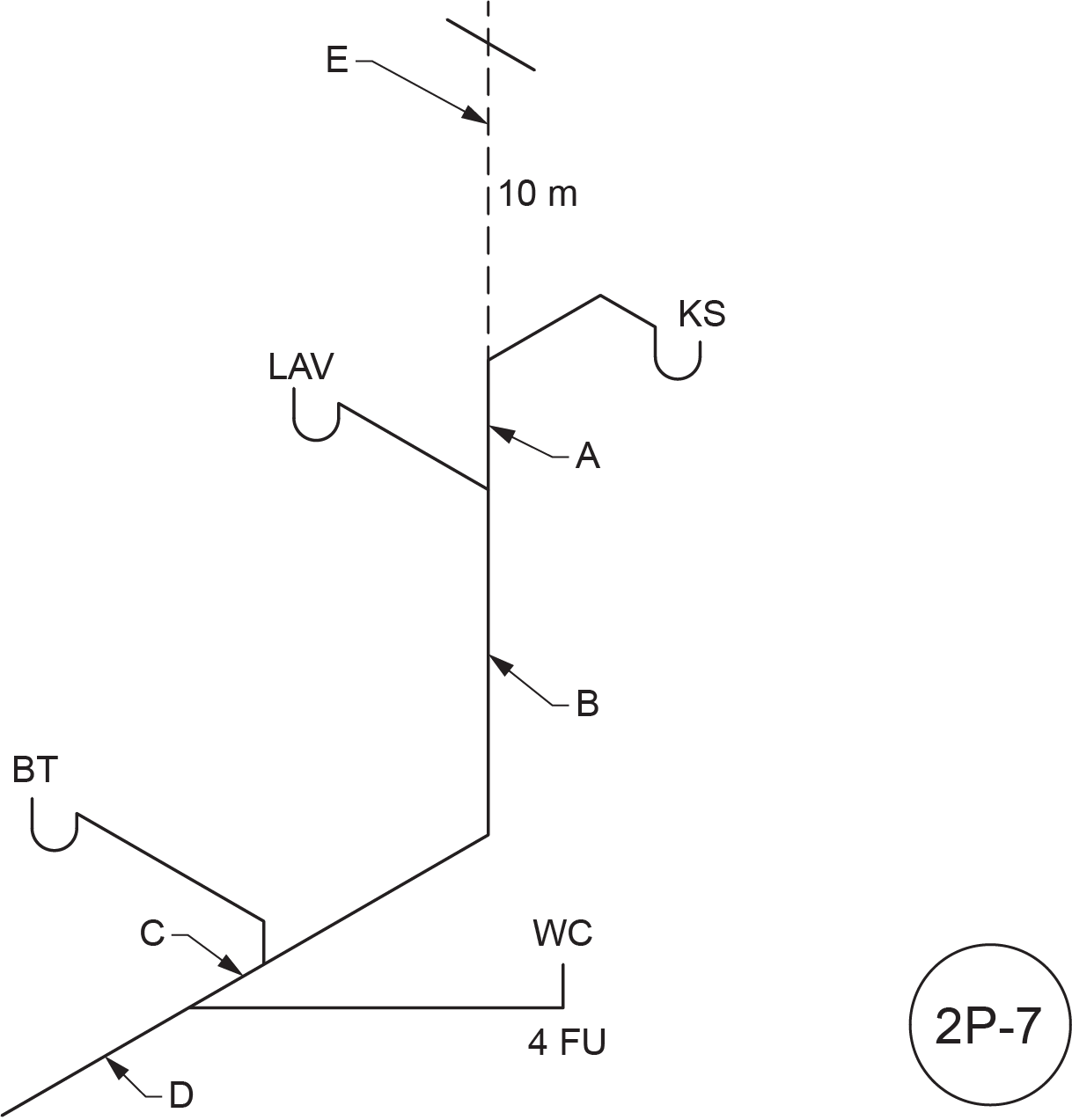 Figure 2P-7
Table 1
| Letter |
Name |
Hydraulic Load (FU) |
Length |
Size |
| A |
|
|
|
|
| B |
|
|
|
|
| C |
|
|
|
|
| D |
|
|
|
|
| E |
|
|
|
|
- Using Figure 2P-8, fill in Table 2 by identifying and sizing the wet vent installation as per the NPC.
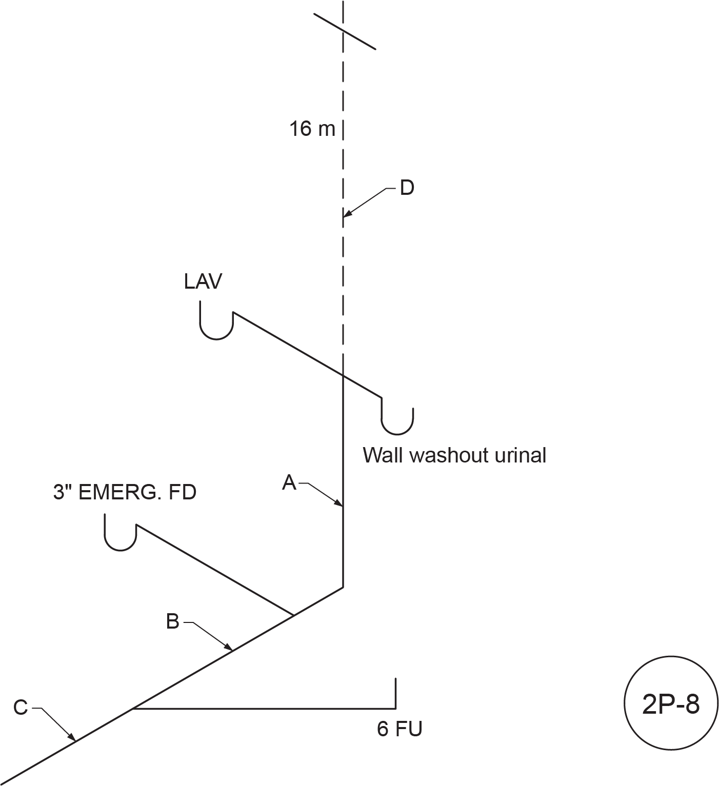 Figure 2P-8
Table 2
| Letter |
Name |
Hydraulic Load (FU) |
Length |
Size |
| A |
|
|
|
|
| B |
|
|
|
|
| C |
|
|
|
|
| D |
|
|
|
|
- Using Figure 2P-9, fill in Table 3 by identifying and sizing the wet vent installation as per the NPC.
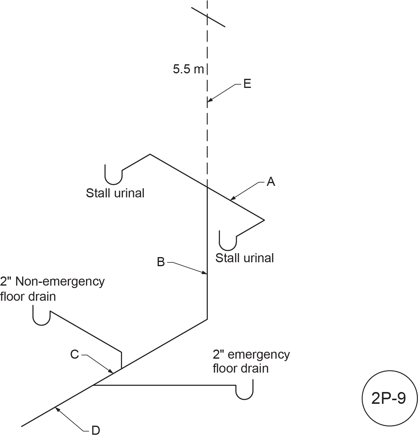 Figure 2P-9
Table 3
| Letter |
Name |
Hydraulic Load (FU) |
Length |
Size |
| A |
|
|
|
|
| B |
|
|
|
|
| C |
|
|
|
|
| D |
|
|
|
|
| E |
|
|
|
|
- Using Figure 4, fill in Table 4 by identifying and sizing the wet vent installation as per the NPC.
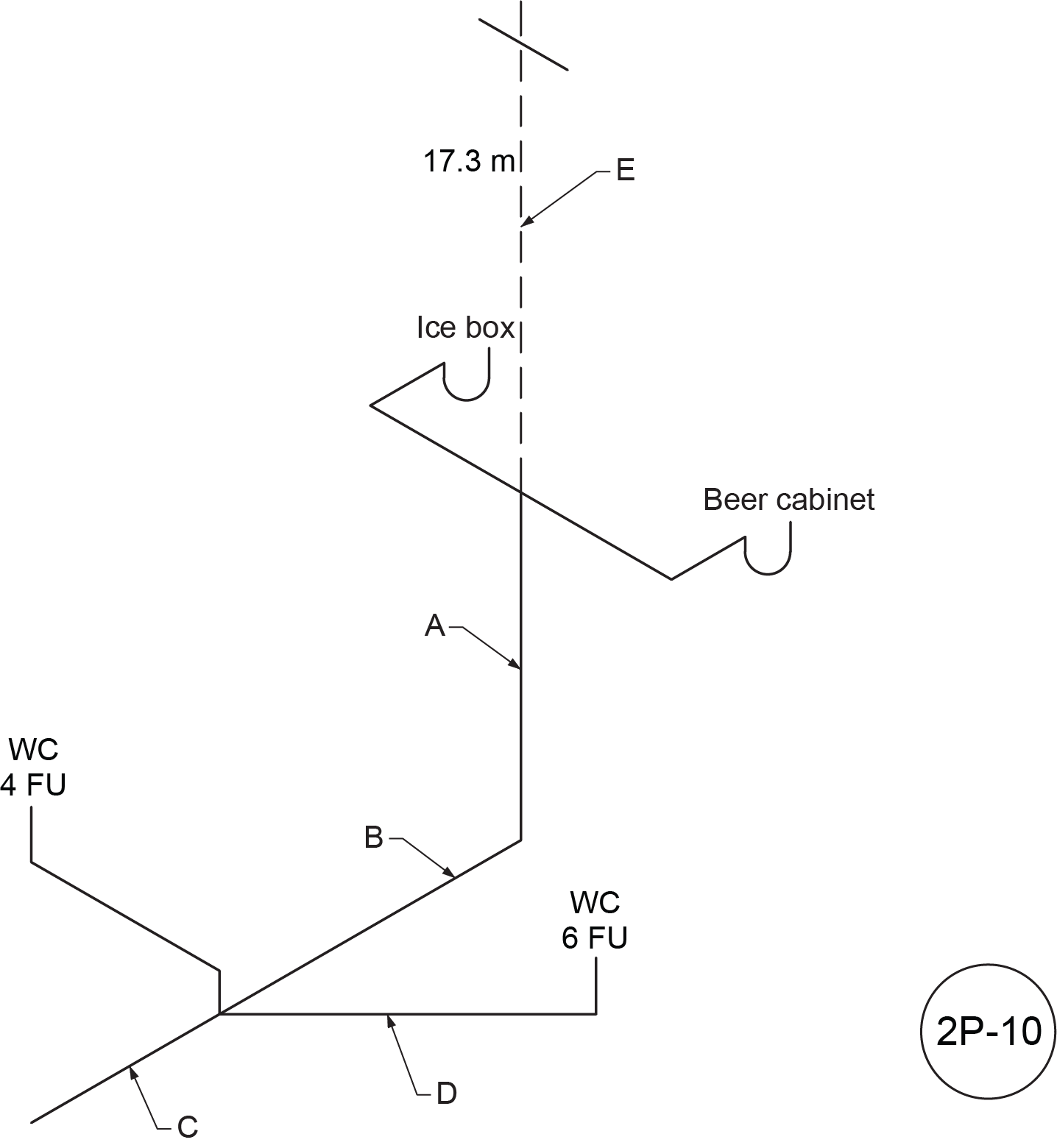 Figure 2P-10
Table 4
| Letter |
Name |
Hydraulic Load (FU) |
Length |
Size |
| A |
|
|
|
|
| B |
|
|
|
|
| C |
|
|
|
|
| D |
|
|
|
|
| E |
|
|
|
‘ |
- Using Figure 2P-11, fill in Table 5 by identifying and sizing the wet vent installation as per the NPC.
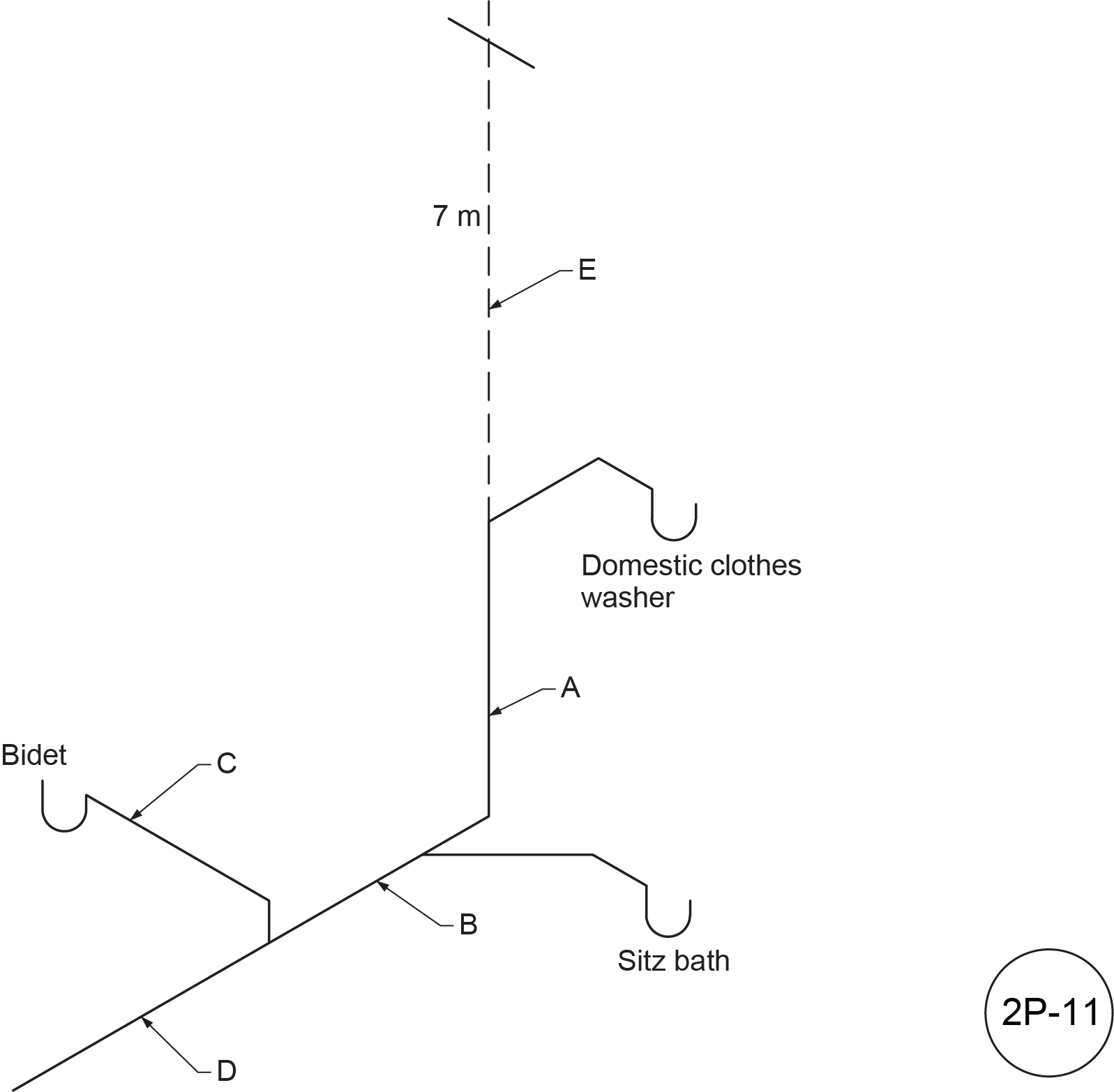 Figure 2P-11
Table 5
| Letter |
Name |
Hydraulic Load (FU) |
Length |
Size |
| A |
|
|
|
|
| B |
|
|
|
|
| C |
|
|
|
|
| D |
|
|
|
|
| E |
|
|
|
|
- Using Figure 2P-12, fill in Table 6 by identifying and sizing the wet vent installation as per the NPC.
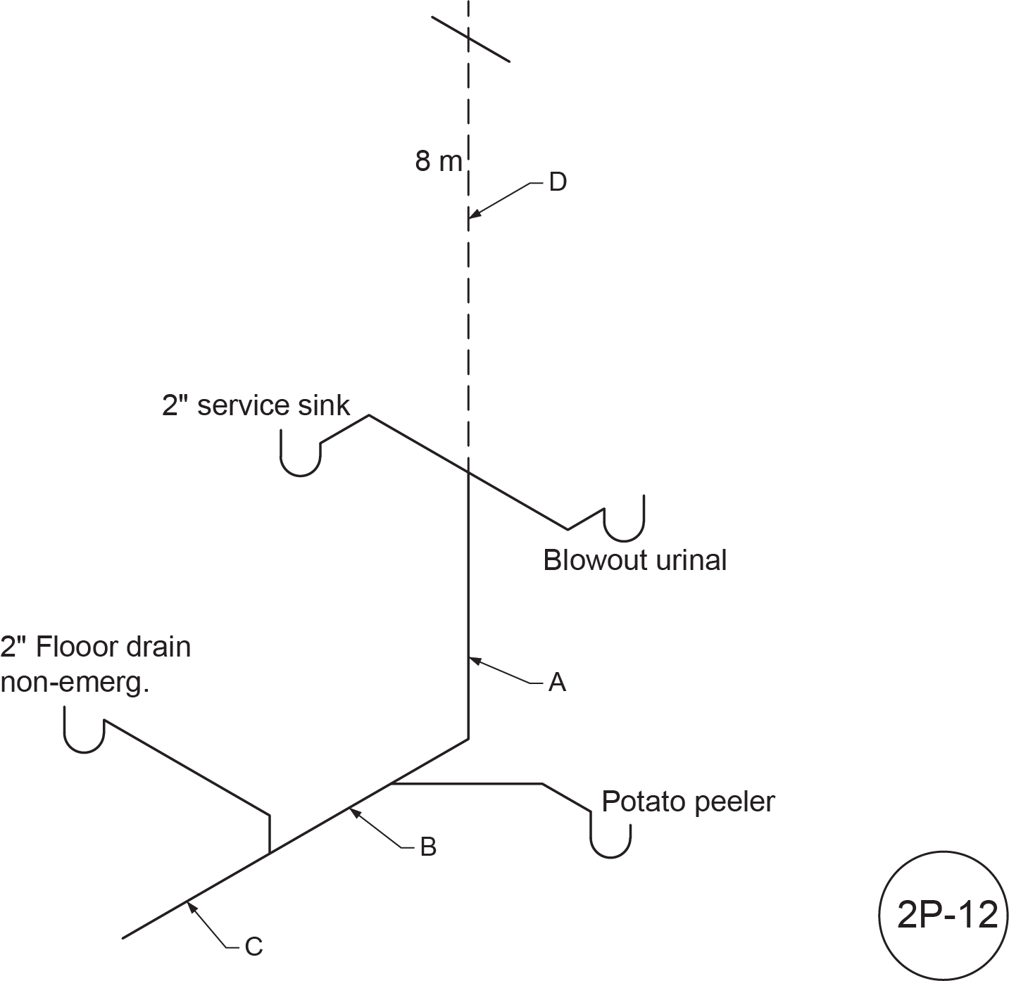 Figure 2P-12
Table 6
| Letter |
Name |
Hydraulic Load (FU) |
Length |
Size |
| A |
|
|
|
|
| B |
|
|
|
|
| C |
|
|
|
|
| D |
|
|
|
|
- Using Figure 2P-13, fill in Table 7 by identifying and sizing the wet vent installation as per the NPC.
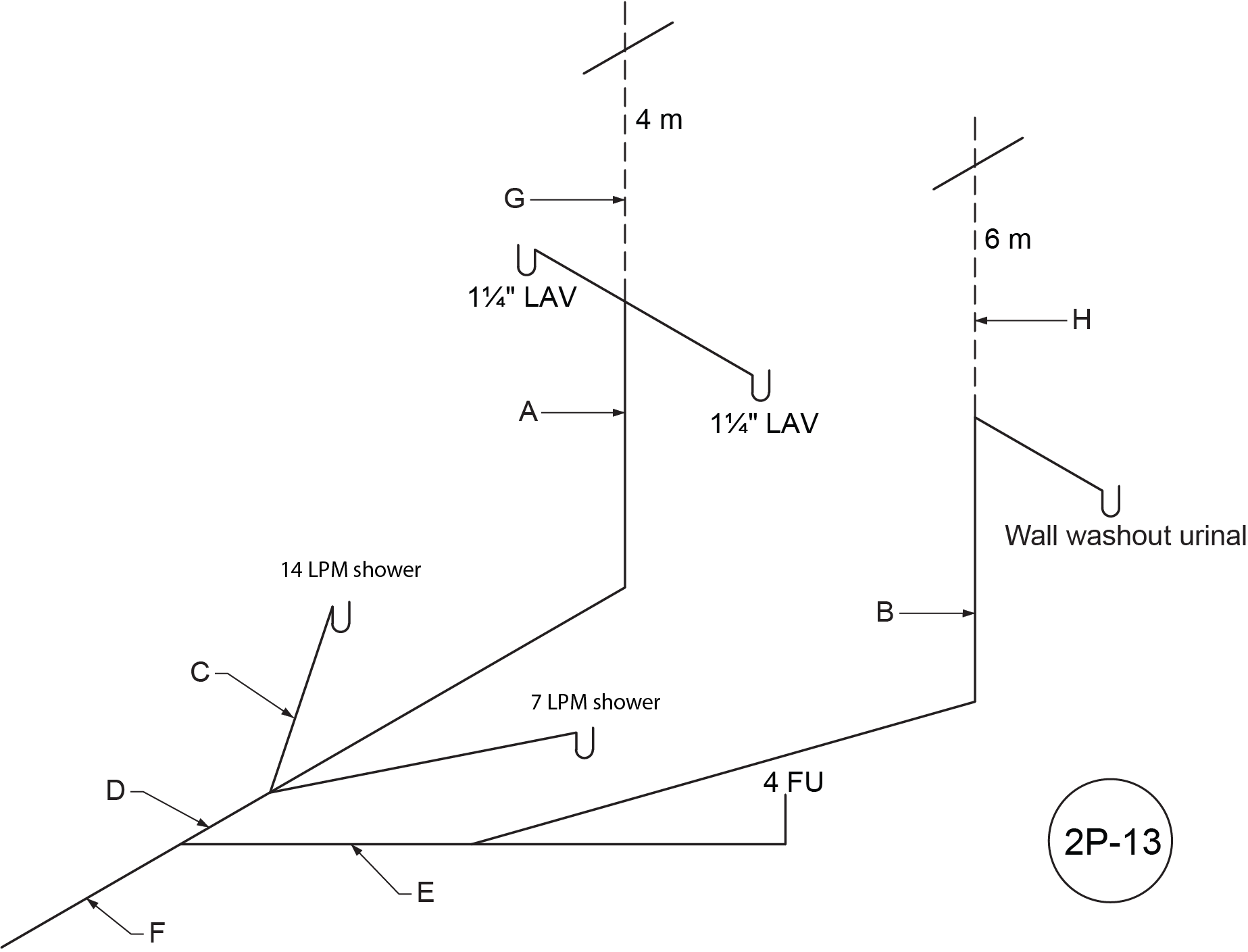 Figure 2P-13
Table 7
| Letter |
Name |
Hydraulic Load (FU) |
Length |
Size |
| A |
|
|
|
|
| B |
|
|
|
|
| C |
|
|
|
|
| D |
|
|
|
|
| E |
|
|
|
|
| F |
|
|
|
|
| G |
|
|
|
|
| H |
|
|
|
|
- Using Figure 2P-14, fill in Table 8 by identifying and sizing the wet vent installation as per the NPC.
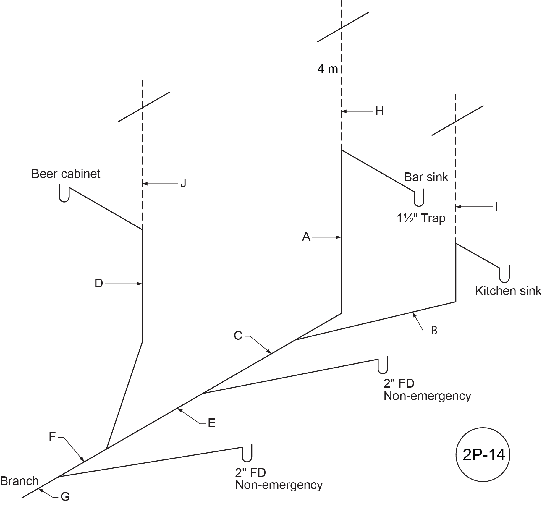 Figure 2P-14
Table 8
| Letter |
Name |
Hydraulic Load (FU) |
Length |
Size |
| A |
|
|
|
|
| B |
|
|
|
|
| C |
|
|
|
|
| D |
|
|
|
|
| E |
|
|
|
|
| F |
|
|
|
|
| G |
|
|
|
|
| H |
|
|
|
|
| I |
|
|
|
|
| J |
|
|
|
|
- Using Figure 2P-15, fill in Table 9 by identifying and sizing the wet vent installation as per the NPC.
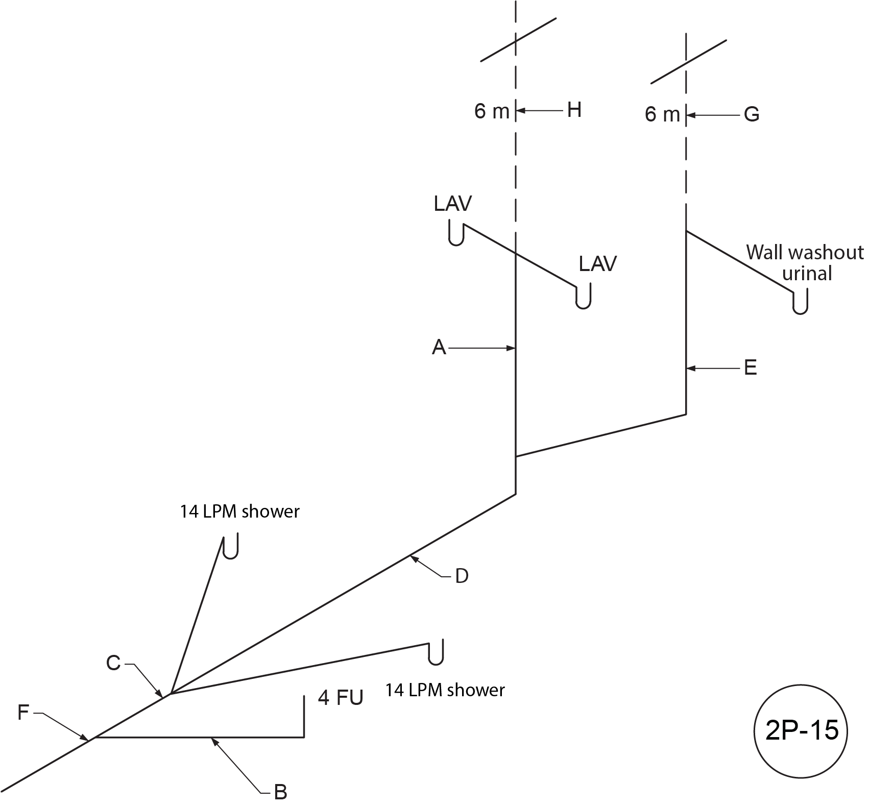 Figure 2P-15
Table 9
| Letter |
Name |
Hydraulic Load (FU) |
Length |
Size |
| A |
|
|
|
|
| B |
|
|
|
|
| C |
|
|
|
|
| D |
|
|
|
|
| E |
|
|
|
|
| F |
|
|
|
|
| G |
|
|
|
|
| H |
|
|
|
|
- Using Figure 2P-16, fill in Table 10 by identifying and sizing the wet vent installation as per the NPC.
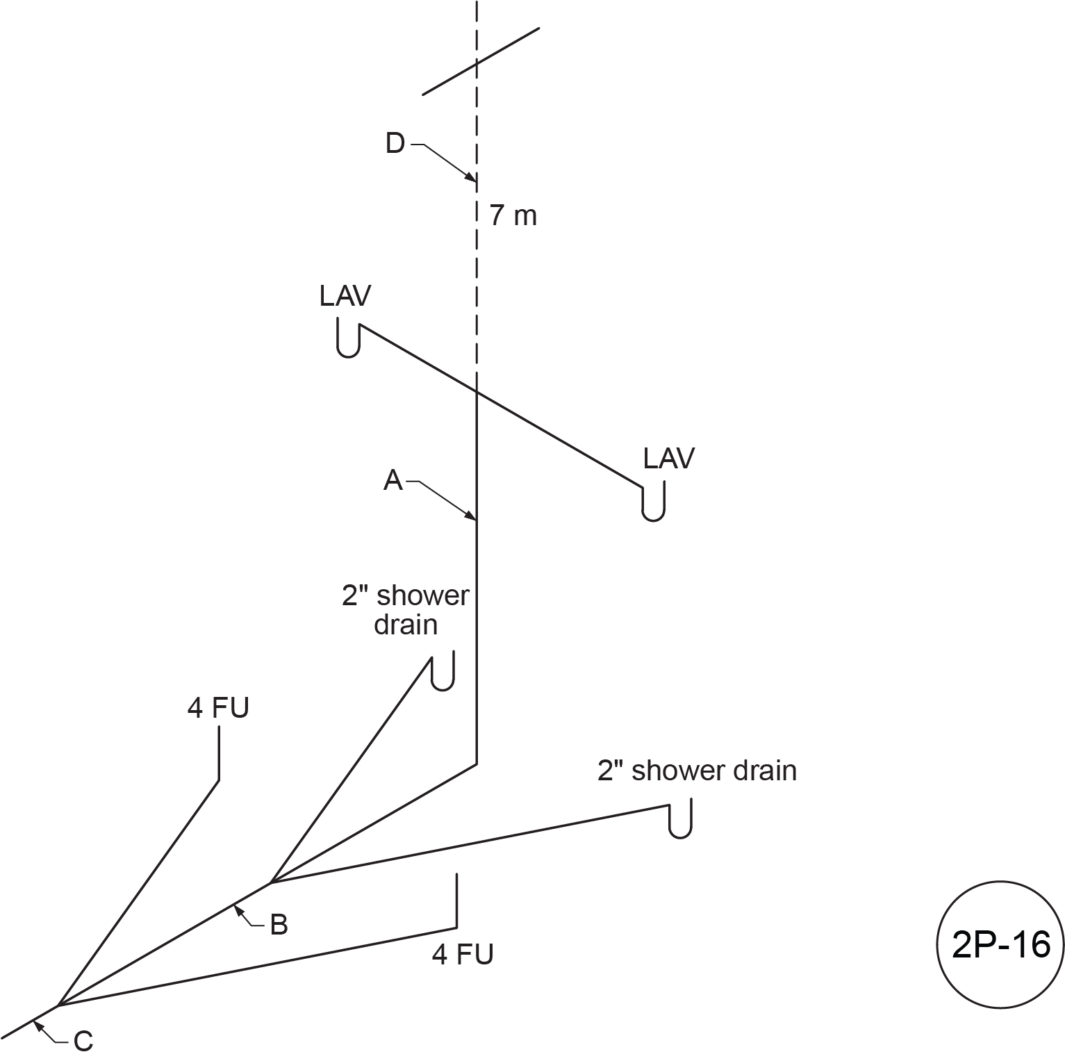 Figure 2P-16
Table 10
| Letter |
Name |
Hydraulic Load (FU) |
Length |
Size |
| A |
|
|
|
|
| B |
|
|
|
|
| C |
|
|
|
|
| D |
|
|
|
|
- Using Figure 2P-17, fill in Table 11 by identifying and sizing the wet vent installation as per the NPC.
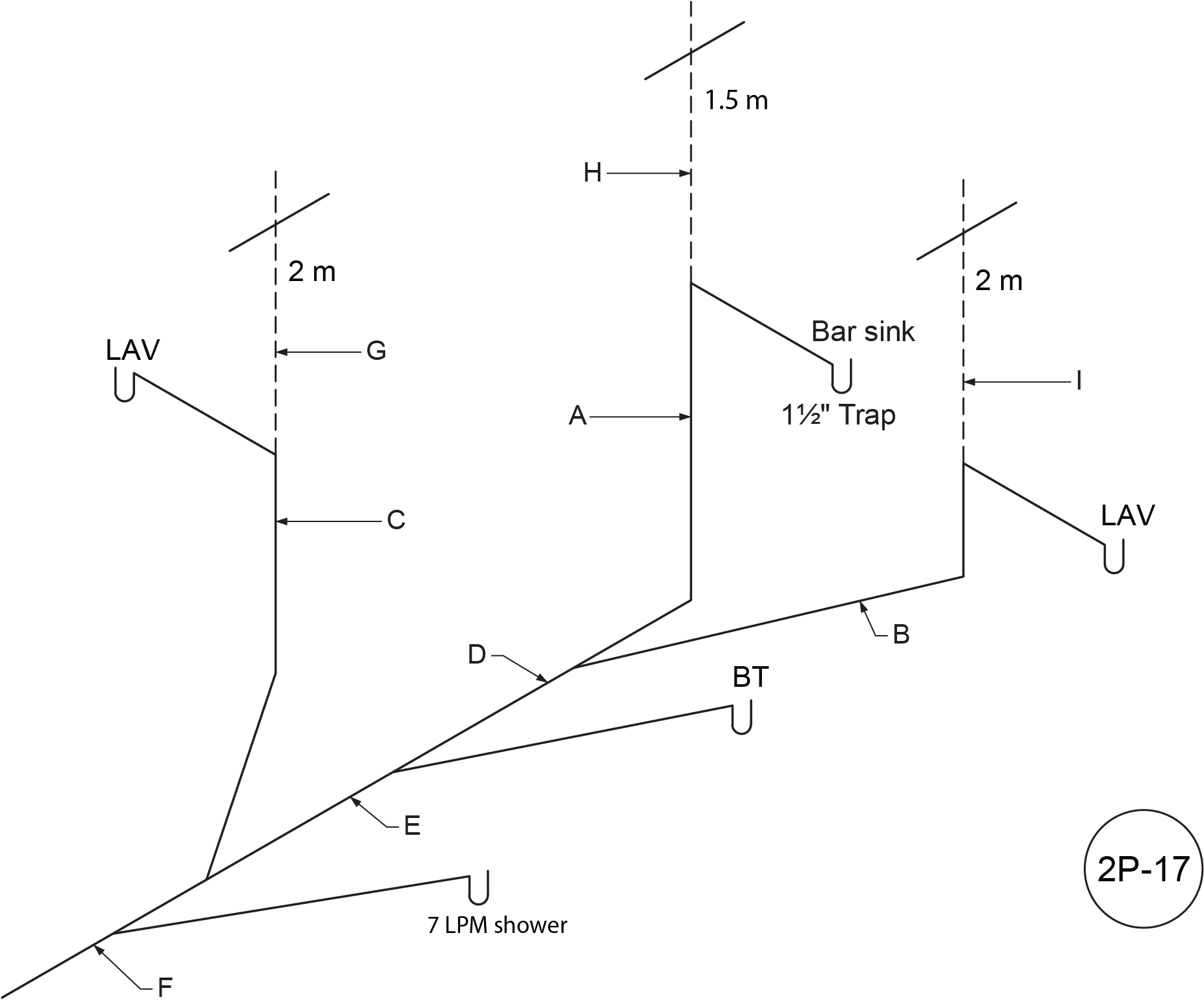 Figure 2P-17
Table 11
| Letter |
Name |
Hydraulic Load (FU) |
Length |
Size |
| A |
|
|
|
|
| B |
|
|
|
|
| C |
|
|
|
|
| D |
|
|
|
|
| E |
|
|
|
|
| F |
|
|
|
|
| G |
|
|
|
|
| H |
|
|
|
|
| I |
|
|
|
|
Answer Key: Self-Test D-1.6 is on the next page.
