D-3.7 Sub-Soil Drainage Systems
Soil stability contributes to the integrity of building structures and public recreational areas as well as to slopes and landscapes that abut highways, subdivisions, septic systems, retaining walls, and the like. Natural soil conditions can vary greatly, and accordingly, their ability to hold or shed water will also vary greatly. The installation of subsoil drainage is often only considered after problems arise, and mitigating any such problems is usually far more expensive, disruptive, and time-consuming than if tackled as a process in the original planning of a project.
Hydrology – from Greek hýdōr meaning “water” and lógos meaning “study” — is the scientific study of the movement, distribution, and management of water on Earth and other planets, including the water cycle, water resources, and environmental watershed sustainability.
“Hydrologic” or “hydrological” engineers belong to a broad range of engineering technologies known as “civil engineering.” Their studies and findings have been widespread, well-documented, and full of terminologies that the average journeyperson may find hard to understand. Fortunately, most hydrologic-based information that the average plumber deals with is contained within jobsite blueprints, specifications, and applicable code books and is presented in a manner intended to be deciphered by non-engineers.
Purpose
Water contained within the soil can cause many problems, such as foundation collapse, sinkholes, mudslides, and other such catastrophes. While predicting such events may not be within the scope of a plumber’s responsibilities, the use and application of sound industry principles and practices that an average plumber is expected to display in order to prevent them is.
Within the National Plumbing Code of Canada (NPC) and the BC Plumbing Code (BCPC), a “subsoil drainage pipe” is defined as “a pipe that is installed underground to intercept and convey subsurface water.” Although no official definition exists in any of the model codes used in building in Canada, the most commonly held definition of “subsurface water” is “water that exists below the ground level.”
Typical Locations for Subsoil Drainage
One of the most critical and common instances of having to deal with subsurface water is in the placing of footing drains for a building. The composition of soil can vary greatly, and although the practice of pouring concrete footings on rock or compacted granular fill may deter the retention of water below the footings, the act of installing a subsoil drainage system around the footings is widely accepted as the norm for all footing placements.
Regulations
The BC Building Code (BCBC), Sentence 9.15.3.2 (1) states, “Footings shall rest on undisturbed soil, rock or compacted granular fill.”
Section 9.14 of the BCBC specifies requirements for surface and subsurface drainage. Sentence 9.14.1.2(1) states, “Drainage for crawl spaces shall conform to Section 9.18”, and Sentence 9.14.1.3(1) specifies that “Drainage requirements beneath floors-on-ground shall conform to Section 9.16.” The following points covered will be limited to those found in Sections 9.14.2 to 9.14.6, which focus on foundation wall drainage (9.14.2), drainage tile and pipe (9.14.3), drainage disposal (9.14.5), and surface drainage (9.14.6).
Subsoil Drainage for Building Footings
Subsoil drainage maintains the integrity of the ground under footings. By removing moisture, soil strength is stabilized, and the possibility of major foundation settlement is greatly reduced or eliminated entirely.
Sentence 9.14.2.1 (1) of the BCBC states “Unless it can be shown to be unnecessary, the bottom of every exterior foundation wall shall be drained by drainage tile or pipe laid around the exterior of the foundation in conformance with Subsection 9.14.3. or by a layer of gravel or crushed rock in conformance with Subsection 9.14.4.”
BCBC Section 9.14.3.3 states that “Drain tile or pipe shall be laid on undisturbed or well-compacted soil so that the top of the tile or pipe is below the bottom of the floor slab or the ground cover of the crawl space.” Figure 1 shows the standard installation for drainage systems around footings.
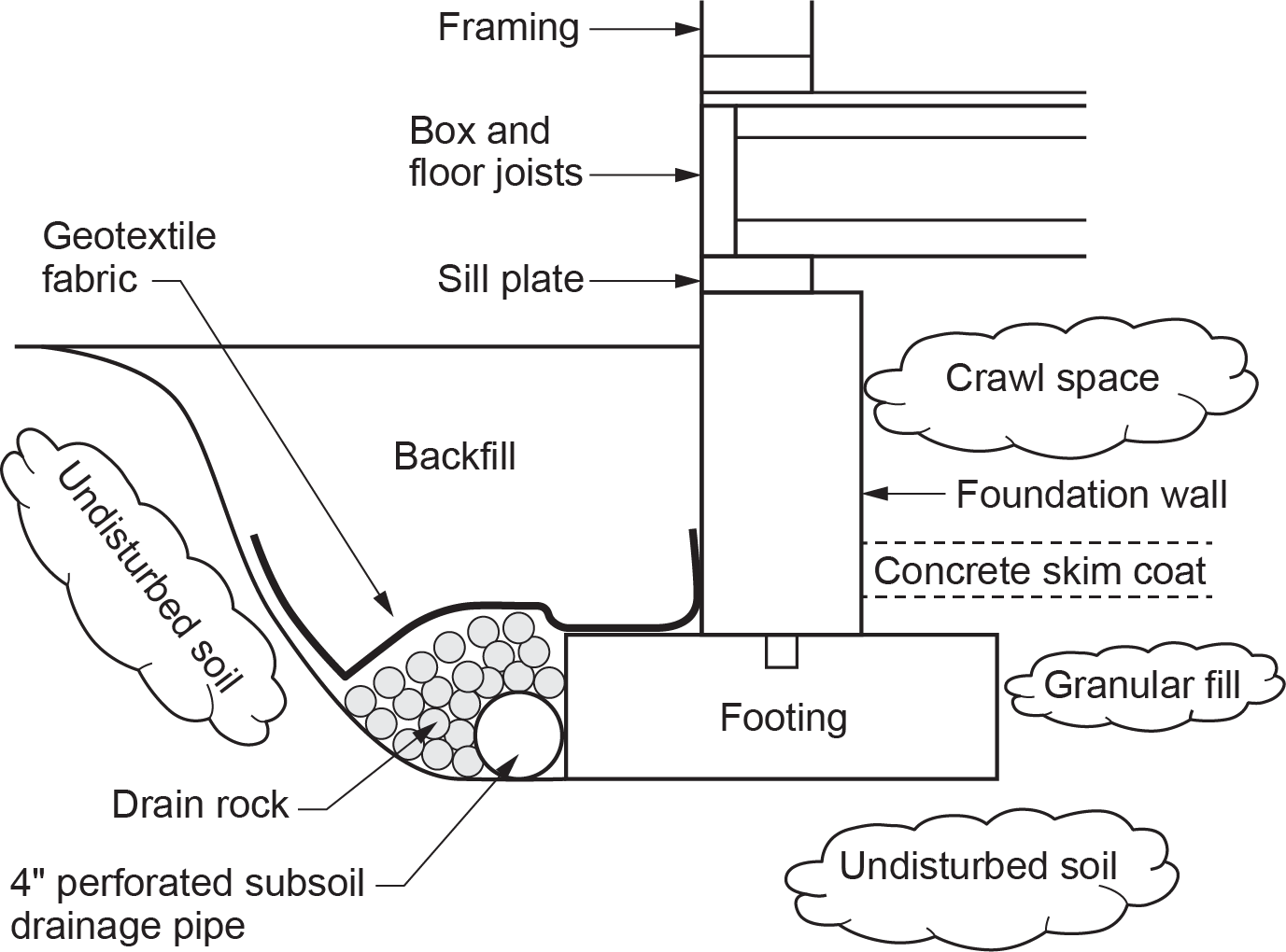
Although available in other sizes, 9.14.3.2. of the BCBC specifies “Drain tile or pipe used for foundation drainage shall be not less than 100 mm in diameter.”
Although not specifically referenced in the codes, the backfill of a perforated pipe is protected from being plugged with fines and silt using a geotextile fabric (landscaping cloth or filter fabric) between the drain rock and backfill, as was shown in Figure 1. This practice is in use in virtually all instances where perforated pipe is installed underground.
Piping Materials
Subsection 9.14.3 of the BCBC lists the acceptable materials that can be used as drainage pipe — which are clay, concrete, plastic, and corrugated steel — and the standards that they must be certified to in order to be acceptable for installation. Of these, plastic is today’s material of choice for most subsoil drainage applications.
Drain Tile
“Drain tile” refers to a type of pipe that, although still found in place, has been replaced by perforated plastic pipe. Subsequent to the use of wood stave piping but before the development of cast-iron pipe, clay was formed into pipe lengths and fired in kilns to become vitrified (hard and glass-like) and, as such, was known as “vitreous clay pipe” (Figure 2). It was heavy, brittle, and very corrosion-resistant. Its main uses were in acid waste systems and in subsoil systems.
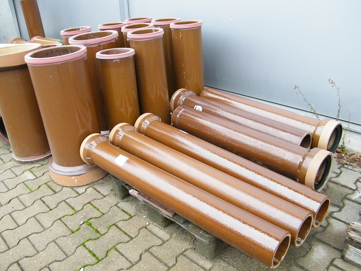
For subsoil systems, 3 in. or 4 in. diameter clay pipe (Figure 3) was formed into short lengths (tiles) of between 8 in. and 12 in. in length that often had an octagonal outer profile.
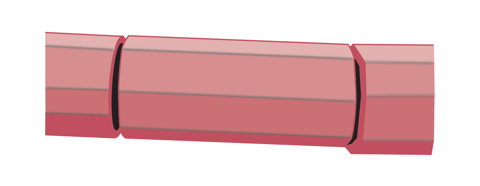
The short lengths were laid end-to-end with a 0.25 in. to 0.50 in. space between them and covered with building paper or some other material to prevent the introduction of “fines” (small particles of dirt or silt) that would otherwise plug the openings. They were used extensively in sewage disposal fields and also to collect and channel away the water that might collect around footings until the advent of perforated plastic pipe. The terms “weeping tile” and “agriculture tile” were also given to this type of pipe because of the ways it was used.
Perforated Pipe
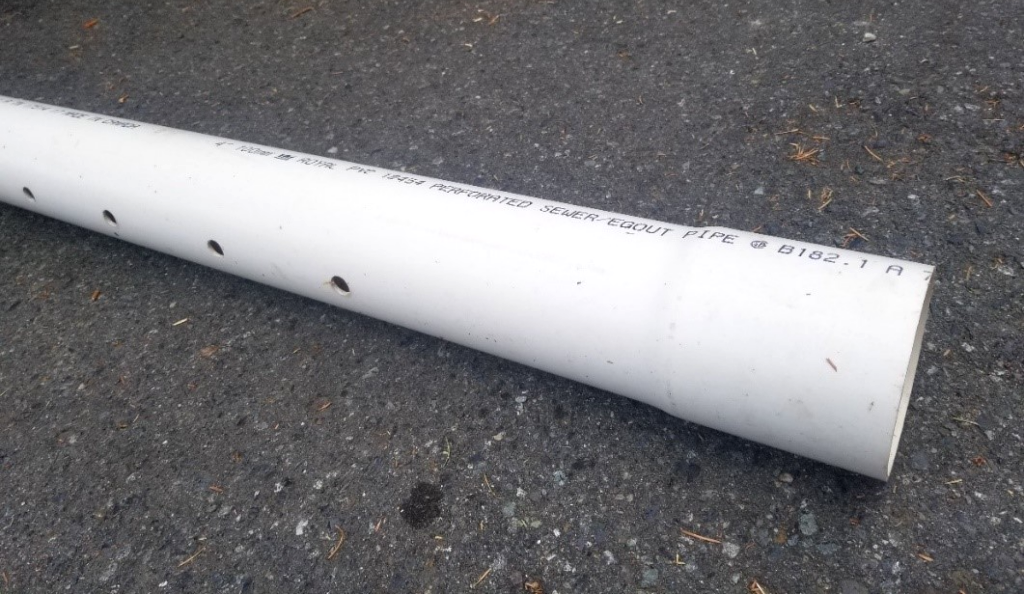
Clay tile pipe was replaced decades ago by perforated PVC plastic pipe. It is most commonly 3 in. or 4 in. in diameter and in lengths of either ten or thirteen feet. Although pipe is available that has perforations around its full circumference and length, the type most commonly used has two lines of 0.50 in. diameter holes spaced along the pipe’s length 120° apart (Figure 4). The holes are positioned at the bottom of the pipe when being installed. The joints can be solvent-welded together, although leakage from the joints would be a redundant issue for most uses.
Corrugated Pipe
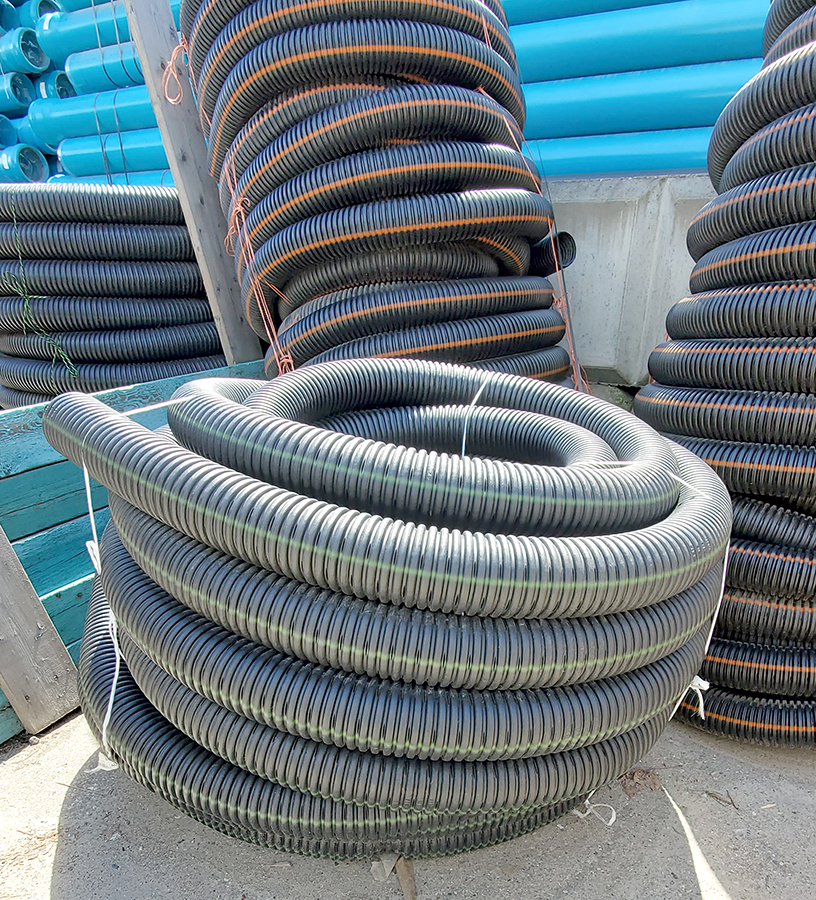
Another form of perforated plastic pipe is made of flexible corrugated polyethylene and is available in coils of 4 in. in diameter that are either 200 or 250 ft long (Figure 5). The perforations are quite small and so are more easily plugged by fines than PVC pipe. It is a common choice for agricultural applications where a constant even grade is not available.
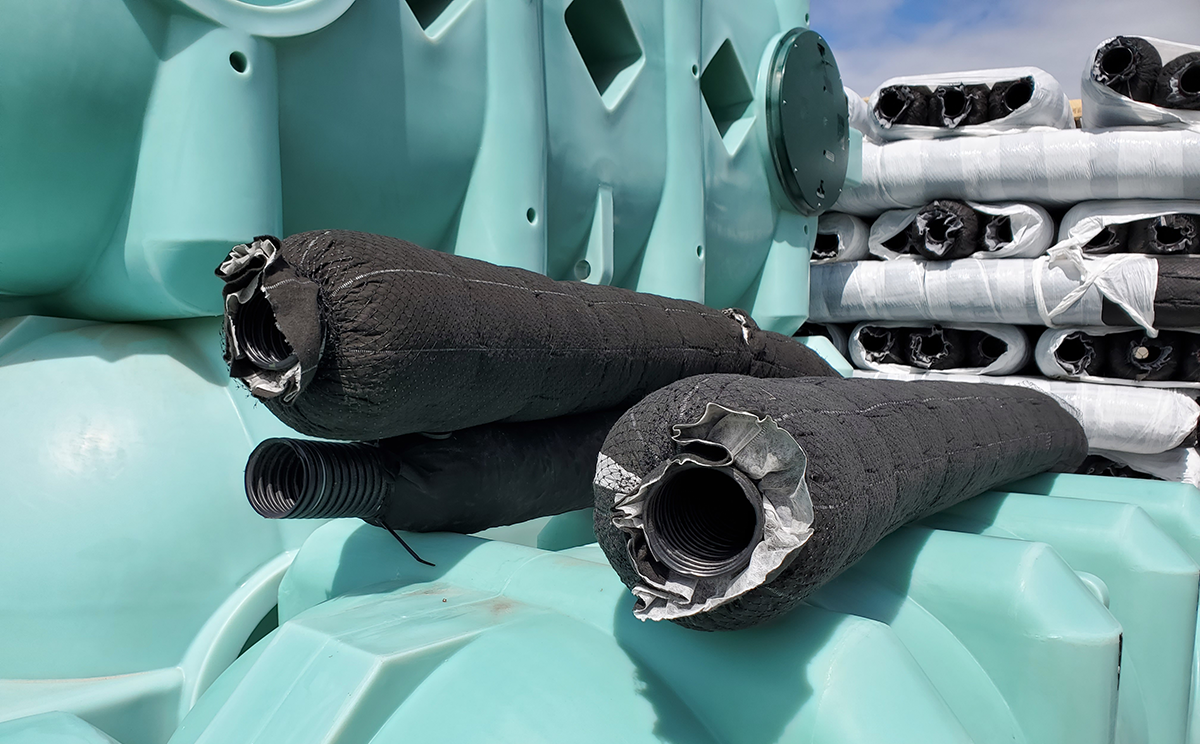
Perforated polyethylene pipe is also available with the geotextile fabric pre-installed, as seen in Figure 6.
Subsoil Drainage Discharge
Sentence 9.14.5.1 (1) of the BCBC specifies that “Foundation drains shall drain to a sewer, drainage ditch or dry well.” Drainage to a sewer is expected to be accomplished by first dumping any footing drain discharge into a sump. In doing so, any debris is removed. The specifics of the sump construction for this application are found in Article 9.14.5.2 and are as follows:
- Where a sump pit is provided it shall be:
- Not less than 750 mm deep,
- Not less than 0.25 m2 in area, and
- Provided with a cover.
- Covers for sump pits shall be designed:
- To resist removal by children, and
- To be airtight in accordance with Sentence 9.25.3.3.(7).
- Where gravity drainage is not practical, an automatic sump pump shall be provided to discharge the water from the sump pit described in Sentence (1) into a sewer, drainage ditch or dry well.
A drainage ditch, as referenced in the code clauses above, is a common and acceptable termination point for most subsoil drainage systems. Many residential properties have ditches that abut the property line and are naturally used for such purposes.
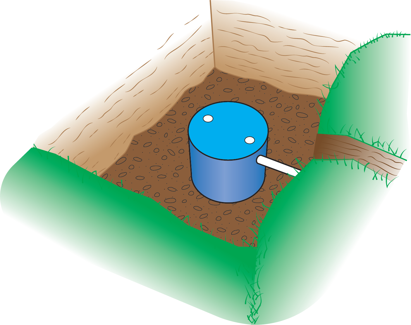
In the absence of a drainage ditch, a dry well or rock pit can be used. It need not be anything more elaborate than an excavated hole in the ground filled with drain rock, into which the drainage pipe is inserted. The dispersal of water from it is more localized than would occur if using a horizontal trench and drain rock. Any discharge from the pipe is expected to percolate (seep) into the soil within a relatively small area. Dry wells may have a perforated tank or drum that acts as a reservoir to provide more volume of initial fill (Figure 7). Regardless of the type of reservoir chosen, it would have to be capable of supporting the ground above it.
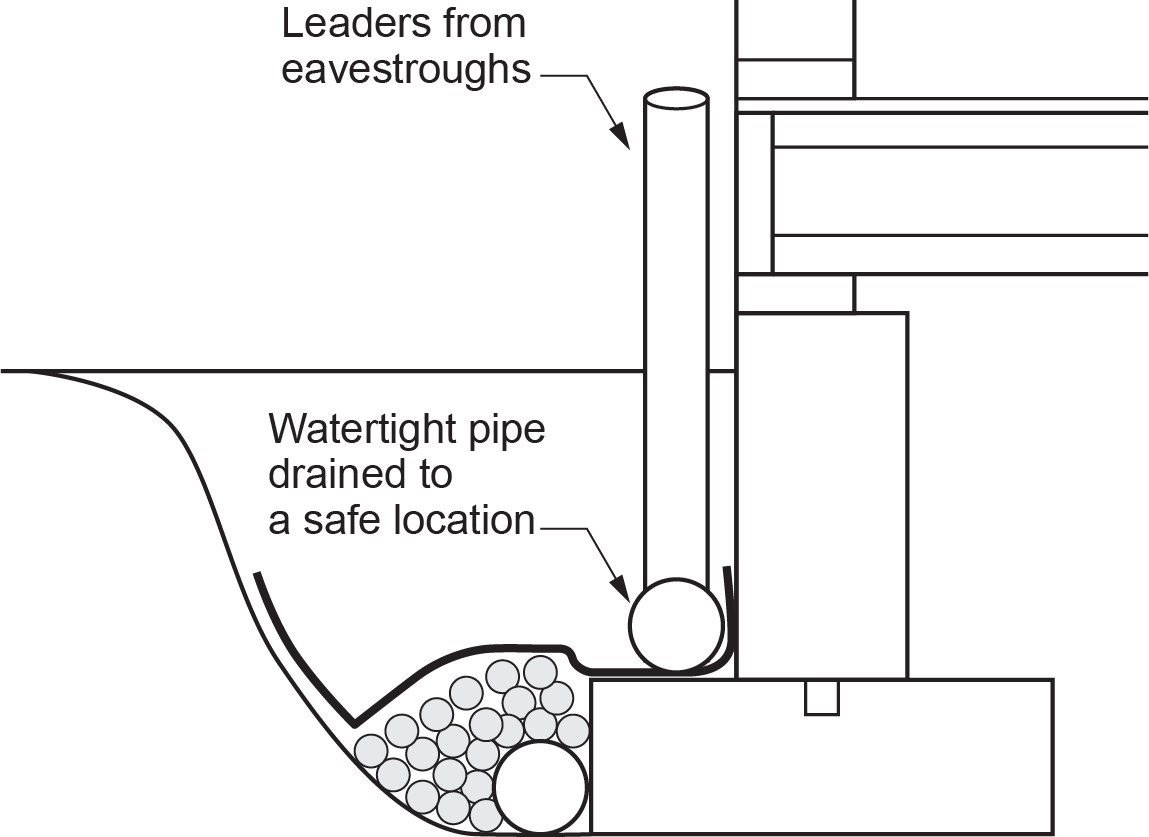
Many houses and buildings built in the latter half of the 20th century combined water from roof drains and eavestroughs with that from the footing drainage system. This was done primarily as a cost-saving measure. Tees were installed in the drain tile surrounding the footings at the locations where the vertical leaders or downspouts were to be located, and pipe was extended to just above ground level, where they connected to the bottom of the leaders. This method proved to be problematic, as the extra water from the leaders often found its way under the footing and into the building if the footing drainage system became restricted or plugged. This is no longer done. As seen in Figure 7, the roof drainage is directed into a separate system of watertight piping that encircles the building and usually discharges into the same termination point as the footing drain.
There are certain areas of the country where subsoil drains, such as from footings, are brought inside the building and tied into the sanitary drainage system. Sentence 2.4.6.4 (6) of the NPC and BCPC specify that the subsoil piping is to be protected from surcharge (backflow from the sanitary systems into the subsoil piping) by installing a gate valve or a backwater valve. This is illustrated in Note A-2.4.6.4 (6) of the code.
Other Subsoil Drains
There are many other types of subsoil drainage systems not covered in the building code because they are designed to control excess water on various landscapes, often for agricultural purposes, rather than for building protection.
French Drains
In 1859, in Concord, Massachusetts, a judge and farmer named Henry French developed an effective way to prevent surface water from ponding by collecting it and channelling it away. He published his concepts in a book with the exhaustive title of Farm Drainage; The Principles, Processes, and Effects of Draining Land with Stones, Wood, Plows, and Open Ditches and Especially with Tiles; Including Tables of Rainfall, Evaporation, Filtration, Excavation, Capacity of Pipes, Cost and Number to the Acre, of Tiles, Etc., Etc.
His concept was thereafter known as a “French drain” and is widely used to this day. There are numerous variations to his original idea, and modern materials have improved its functionality. In government publications in British Columbia, French drains are referred to as “blind inlets.”
A French drain consists of a trench; perforated pipe; clean, washed rock; geotextile fabric; and backfill, as shown in Figure 9.
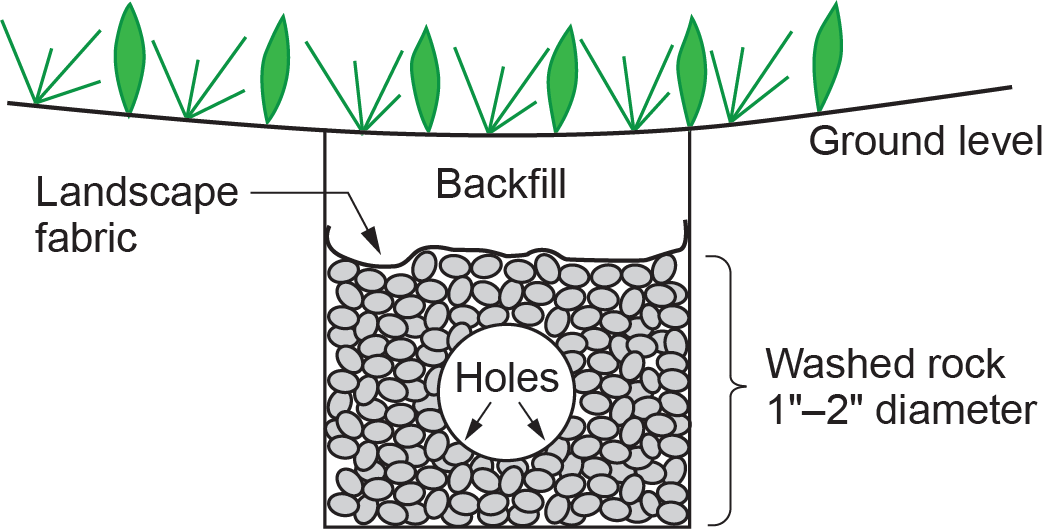
A trench is dug approximately 8 in. (200 mm) wider than the width of the pipe and as deep as needed in order to have a reasonable amount of backfill above the landscape fabric separating the backfill from the rock. A minimum of 2 in. (50 mm) of washed rock is placed in the bottom of the trench below the pipe. The pipe is laid, and the trench is filled with washed rock to at least 2 in. (50 mm) above the pipe. Landscape fabric is laid on top of the washed rock, across the width of the trench, then the trench is backfilled. Note that the perforations (holes) are positioned at the bottom of the pipe.
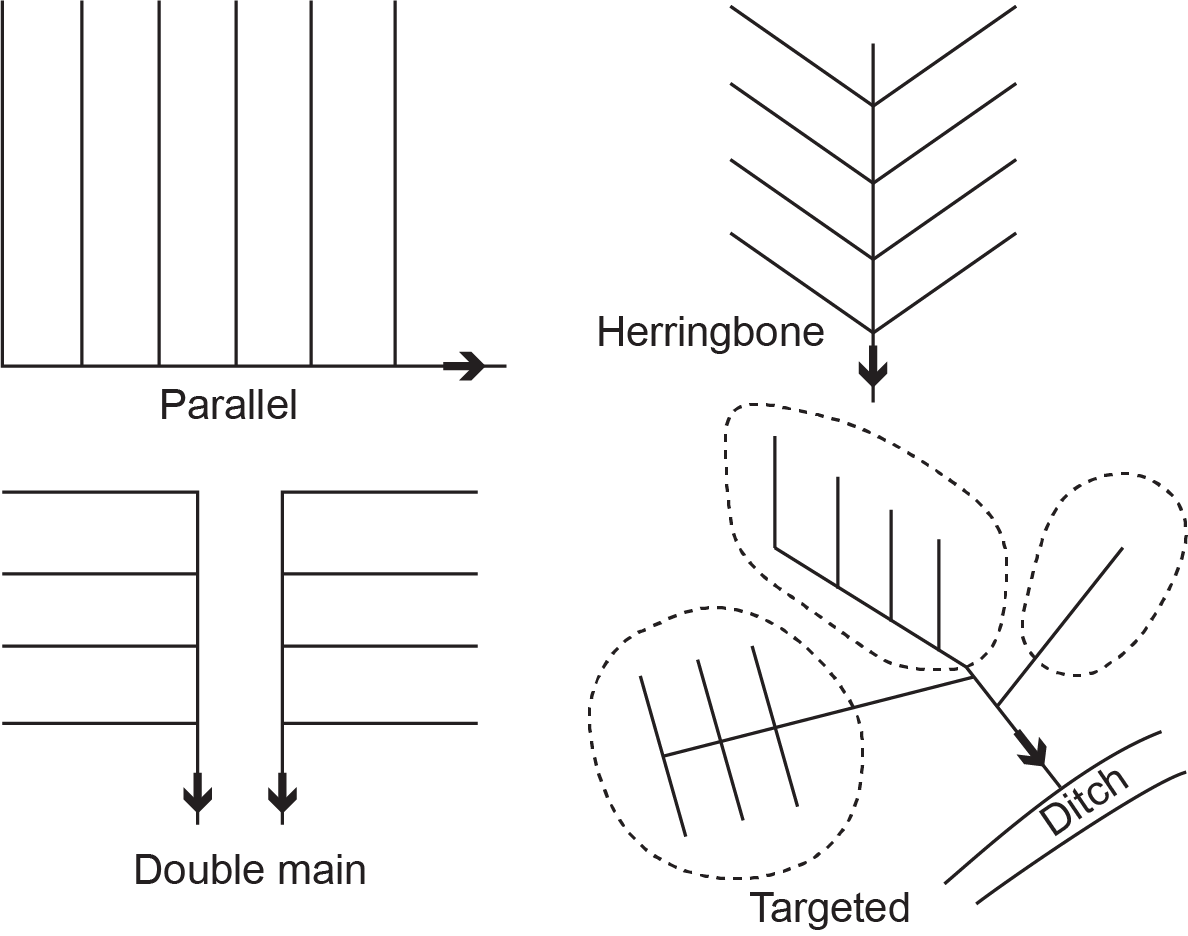
A network of trenches can be installed in a few different configurations to provide coverage over large areas, as seen in Figures 10 and 11.
Curtain Drain
Subsoil drains are typically installed at natural depressions in the ground, which is where ponding usually occurs. This minimizes the amount of sculpting that must be done to the surrounding area in order to direct surface water to desired locations for collection.
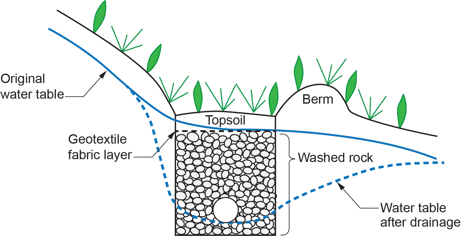
Curtain drains are French drains installed across a slope. Their purpose is to lessen the amount of water that might accumulate on a sensitive surface, such as the disposal field for a septic system, by intercepting and draining it away from the area. As seen in Figure 12, surface runoff is caught in a slight depression created by a buildup of soil on the downstream side of the trench. This is commonly called a berm. The berm holds back water that is allowed to percolate through the thin layer of topsoil into the trench below and be drained away to a more suitable location. Curtain drains lower the water table of the original topography.
Curtain drains are also beneficial when installed at the base of a slope of rock. Almost every drop of rain that contacts the rock face will make its way to the bottom of the slope, with virtually none of it being absorbed into the surface along the way. Ponding and flooding at the base of the slope could otherwise result. A curtain drain located near the slope’s base can help mitigate any accumulation of water.
Mole Drains
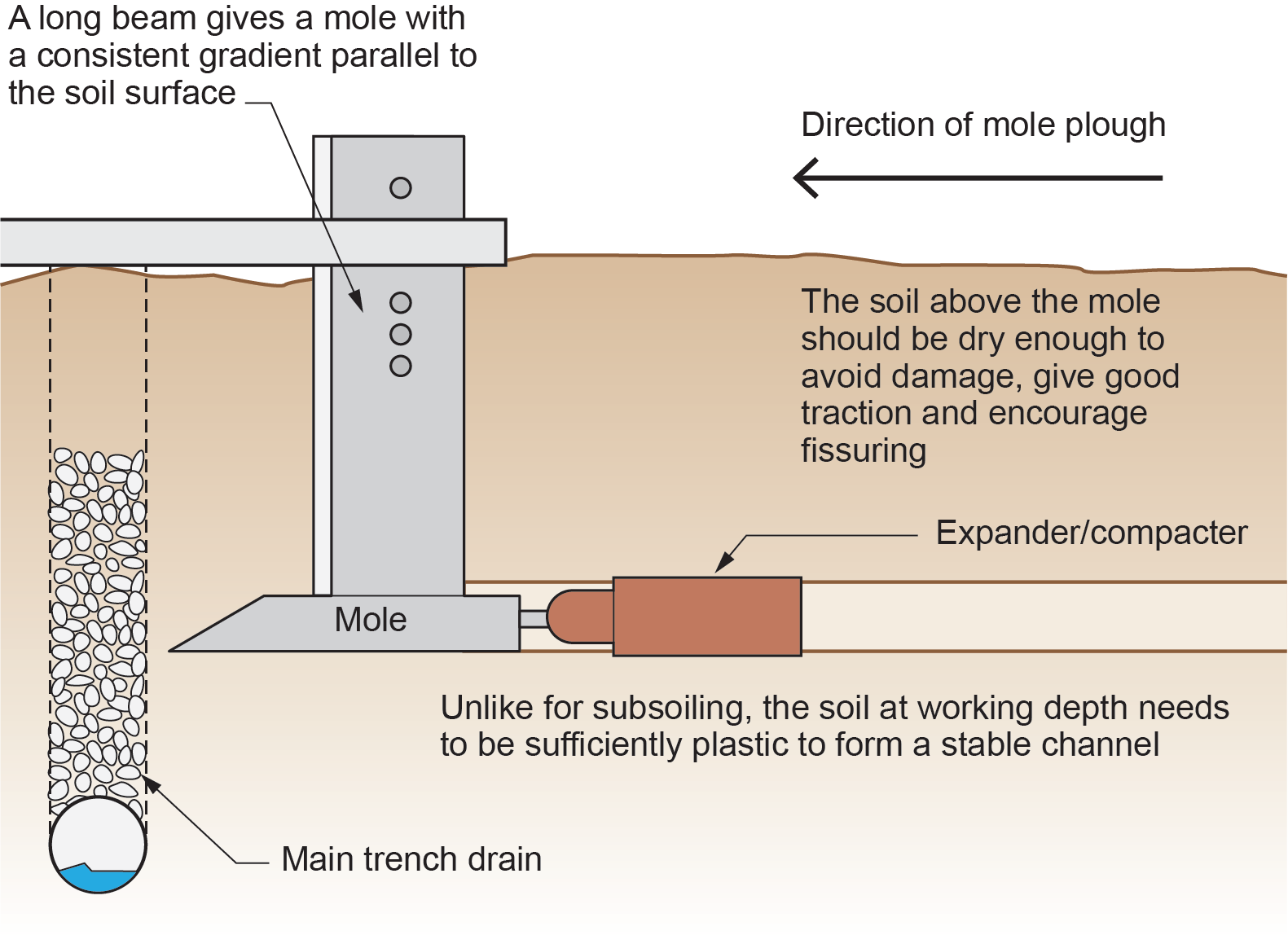
“Moling” is a commonly used process in agriculture whereby a torpedo-shaped mandrel, with an expander/compacter behind it, is pulled through the soil behind a heavy tractor or bulldozer to create a void horizontal space or tunnel below ground. The mole assembly is at the bottom of a very narrow stem or beam that splits the ground cover without leaving a trench or depression. The equipment is often referred to as a “trenchless plow”. Moling can be done with or without pipe being pulled simultaneously behind the expander/compacter into the trench.
Pipeless moling is most commonly used in farming. Soils with high clay content are problematic for farmers because they tend to hold water for great lengths of time once saturated (waterlogged) and have very slow percolation rates, which causes ponding of snow melt and rain in the shoulder seasons. Both situations are detrimental to crop production and can be alleviated by installing a pattern of “moled” channels that lead to a main French drain.
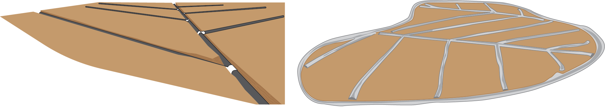
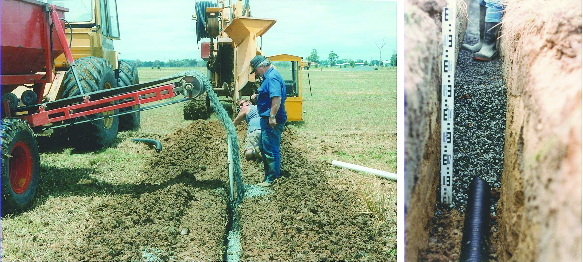
First, a main French or trench drain is installed through the field. Special equipment (Figure 13) is used to trench, install pipe, and drain rock all at the same time and to any chosen elevation below ground. These are normally installed at a recommended depth ranging from 900 mm (3 ft) to a maximum of 1.5 m (5 ft) with an average depth being 1.2 m (4 ft). These depths ensure the pipe will not be contacted by tillers or plows when the field is being cultivated.
Next, a mole is pulled across the field in a grid pattern perpendicular to the main trench. The mole creates tunnels at an elevation that intersects the main trench just above the pipe (Figure 14). Groundwater enters the network or mole drains and follows them to the main trench drain. Discharge from the trench drain is directed to a natural waterway, such as a ditch or stream.
 Self-Test D-3.7: Sub-Soil Drainage Systems
Complete Self-Test D-3.7 and check your answers.
If you are using a printed copy, please find Self-Test D-3.7 and Answer Key at the end of this section. If you prefer, you can scan the QR code with your digital device to go directly to the interactive Self-Test.

References
Skilled Trades BC. (2021). Book 2: Install fixtures and appliances, install sanitary and storm drainage systems. Plumber apprenticeship program level 2 book 2 (Harmonized). Crown Publications: King’s Printer for British Columbia.
Trades Training BC. (2021). D-3: Install storm drainage systems. In: Plumber Apprenticeship Program: Level 2. Industry Training Authority, BC.
Media Attributions
All figures are used with permission from Skilled Trades BC (2021) unless otherwise noted.
- Figure 2: Clay pipe by Tesamoll on Wikimedia Commons was used by Skilled Trades BC (2021) under a CC0 1.0 license.
- Figure 4: Perforated PVC pipe by Rod Lidstone is used under a CC BY license.
- Figure 13: Installing a main French drain [Left image, Right image] by the Western Australian Agriculture Authority was used by Skilled Trades BC [“for non-commerical educational purposes”] under WAAA Copyright terms and conditions.
The ability of soil to remain intact and not shift or collapse, which is crucial for maintaining the integrity of structures and landscapes. (Section D-3.7)
The scientific study of the movement, distribution, and management of water, including the water cycle and water resources. (Section D-3.7)
A branch of engineering that focuses on designing, building, and maintaining things like roads, bridges, buildings, and water systems. Civil engineers work to make sure these structures are safe, strong, and help people live and work better. (Section D-3.7)
The strong, stable foundations or base structures that support the weight of a building or other construction. They help keep the building from sinking or shifting by spreading out the weight evenly onto the ground. Footings are usually made of concrete and are placed below the building to provide solid support, especially for heavy plumbing systems and pipes. (Section D-3.7)
A type of pipe used in drainage systems, often made of clay, that helps collect and move water from the soil, typically used around foundations. (Section D-3.7)
A type of pipe with holes or slits along its length, used in drainage systems to allow water to enter the pipe from the surrounding soil. (Section D-3.7)
A type of pipe made from baked clay that has a smooth, hard surface, like glass. It's used in plumbing and drainage systems because it's strong, durable, and resists wear and tear from water and chemicals. (Section D-3.7)
Small particles of dirt, sand, or silt that are tiny enough to pass through a sieve or filter. These particles can make soil harder to drain because they fill in the spaces between bigger particles. (Section D-3.7)
A large, deep hole filled with rocks or gravel where water can collect and slowly soak into the ground. It is used to manage excess rainwater and help prevent flooding by allowing the water to be absorbed instead of staying on the surface. (Section D-3.7)
A type of pipe fitting shaped like the letter "T" that is used to join three pipes together. It allows water or other liquids to flow in two different directions from one main pipe. (Section D-3.7)
A drainage system consisting of a trench filled with perforated pipe and clean rock, designed to direct surface water away from an area. (Section D-3.7)
A fabric material used in drainage systems to prevent the clogging of pipes by fine particles like silt while allowing water to pass through. (Section D-3.7)
A French drain installed across a slope to intercept and drain water away from sensitive areas, such as septic disposal fields, reducing water accumulation and lowering the water table. (Section D-3.7)
A raised area of soil that is typically built along the edge of a trench or drain to hold back water, directing it into the drain for proper collection and drainage. (Section D-3.7)
A process in agriculture where a torpedo-shaped mandrel creates tunnels or voids in the soil without leaving a visible trench, often used to improve drainage in waterlogged fields. (Section D-3.7)
A type of equipment used in moling that creates a narrow void or tunnel in the soil without disturbing the surface or creating a visible trench. (Section D-3.7)
A type of drain created using moling, where tunnels are formed in the soil to improve water drainage, commonly used in farming to address waterlogged soils with slow percolation rates. (Section D-3.7)
