D-3.2 Functions of Pipes in Storm Drainage Systems
A storm drainage system is composed of storm water collection devices and the associated piping connected to the collection devices that transport the stormwater to an approved disposal location. This chapter describes the array of stormwater collection devices utilized and their function in the system.
Parts and Function
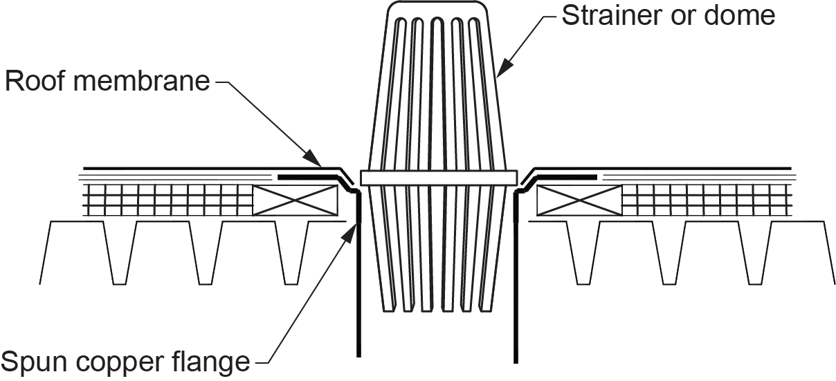
Roof drain: a drain installed through the roof deck or slab. It is generally a circular body made of cast iron with a dome-type strainer that receives stormwater on all sides of the drain. Roof drains are also available in spun copper (Figure 1) or aluminum styles that may or may not be furnished with strainers. Whenever you install a flat roof drain, ensure that strainers or domes are in place to prevent debris and other potential obstruction elements from getting into the drainage system.
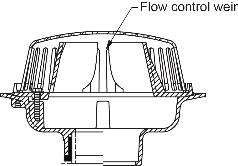
Flow-control roof drain: used to drain the roof at a controlled rate. Excess water is allowed to accumulate on the roof under controlled conditions. The water then drains off at a lower flow rate after a rain event. The roof must be structurally designed to temporarily store the maximum amount of water without overloading during periods of heavy rainfall.
Siphonic roof drain: a drain designed to operate at full pipe capacity, which creates a siphonic condition. The siphonic condition allows water to drain faster than using conventional gravity roof drains. Because of the flow rates generated, a minimal number of roof drains are required, and they can be connected into a single rain leader.
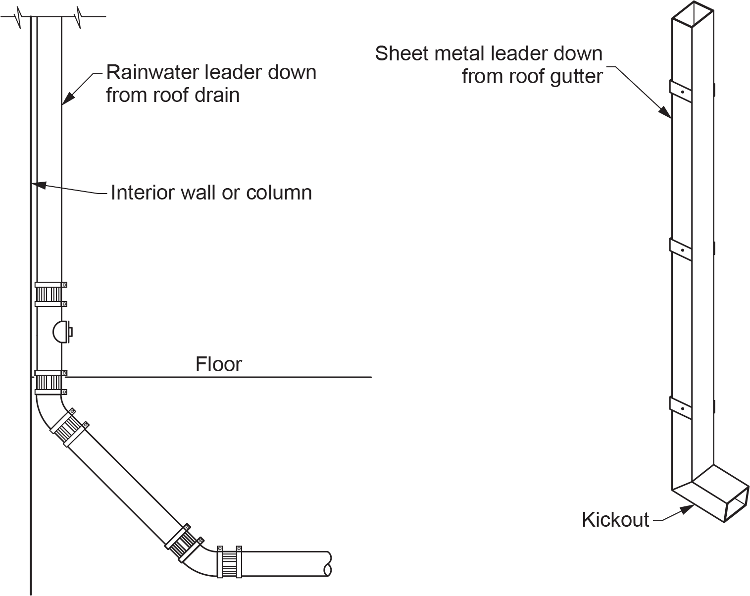
Rainwater leaders (RWL): may be attached to the outside wall of a building or located within a building. They may be a sheet metal leader, a non-circular tubing material, or a pipe (Figure 3).
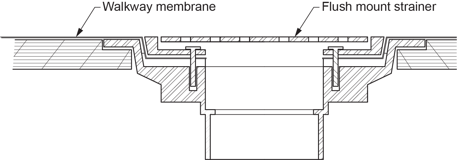
Deck drain: a drain similar in all respects to a roof drain except that it generally has a flat strainer and is located in an area such as a walkway (Figure 4).
Roof gutter: a collection device attached along the entire lower side of a pitched roof. Typically constructed of aluminum or steel with a corrosion-resistant coating and terminating at an external leader.
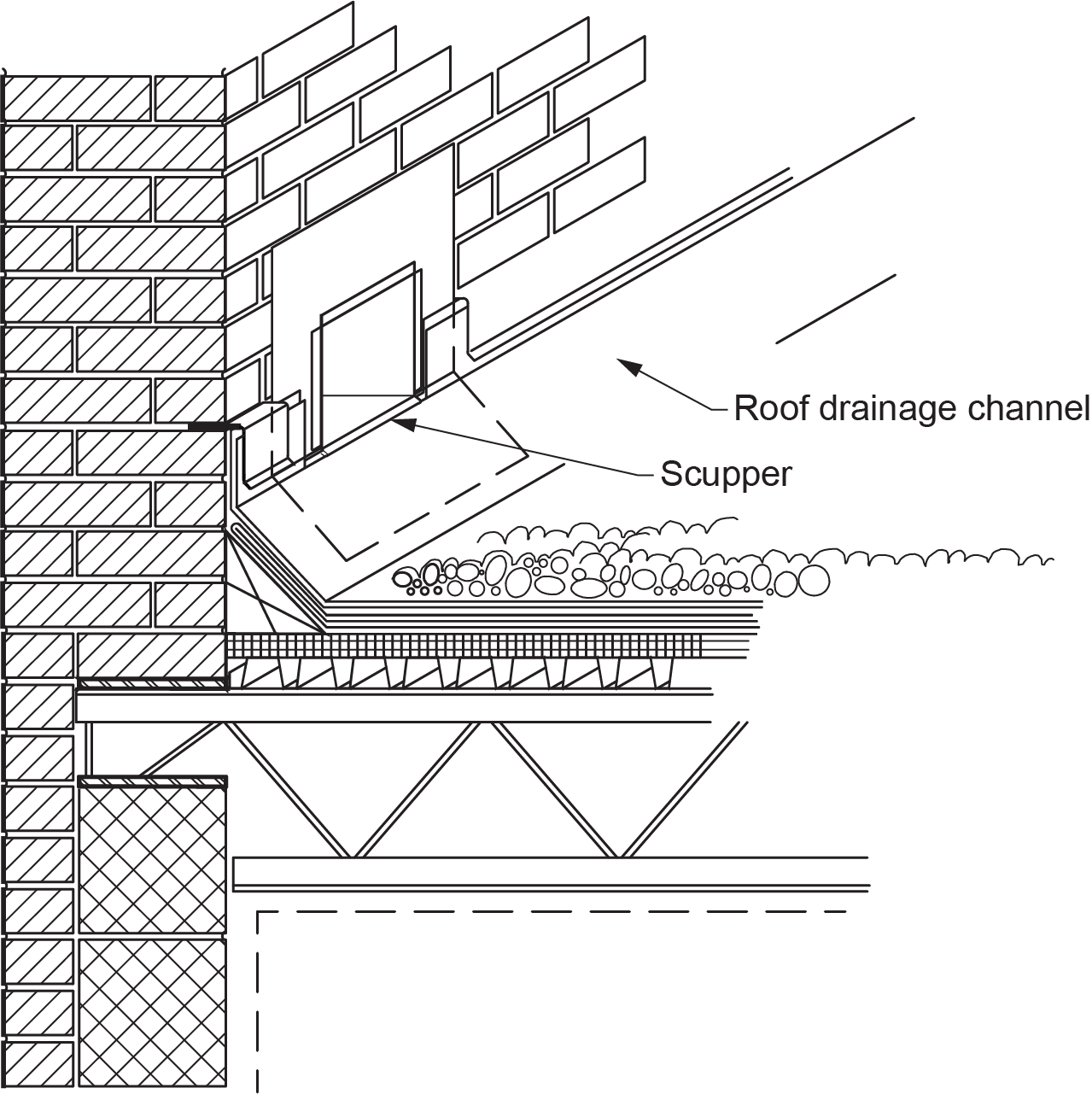
Roof scupper: a box-like collection device located on the exterior of a building and that receives stormwater on one side (Figure 5). Emergency scuppers are designed as overflow protection on flat roofs and are typically installed in conjunction with flow-control roof drains and parapet walls.
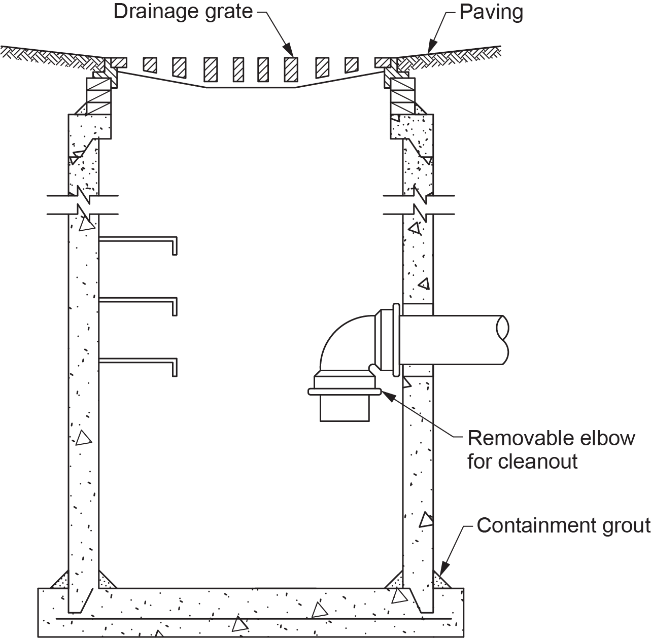
Catch basin: a part of a storm drainage system used to drain paved areas, such as parking lots. Catch basins lead to storm sewers, which release the untreated water through outfalls directly into nearby streams or rivers. It is designed to trap debris to prevent it from entering the drainage pipes (Figure 6).
Storm drainage piping systems: may be designed for gravity or pumped flow to a point of discharge. The AHJ regulates the discharge rate for stormwater systems according to a municipal stormwater management strategy.
Combined drainage piping systems: designed to collect both storm drainage (rainwater and snowmelt) and wastewater (sewage from homes and businesses) in the same pipe. These systems have serious drawbacks because during periods of heavy rainfall or snowmelt, the additional volume in a combined sewer system can exceed the capacity of the sewer system.
Although most jurisdictions have replaced or are replacing these systems with dedicated sewer systems for storm and sanitary drainage, there are existing systems that have not been converted. If this situation exists, some jurisdictions employ combined sewer overflows (CSOs). CSOs are designed to overflow and discharge the excess flow directly to a predetermined disposal area, such as a river, without reaching the sewage treatment plant.
 Self-Test D-3.2: Functions of Pipes in Storm Drainage Systems
Complete Self-Test D-3.2 and check your answers.
If you are using a printed copy, please find Self-Test D-3.2 and Answer Key at the end of this section. If you prefer, you can scan the QR code with your digital device to go directly to the interactive Self-Test.

References
Skilled Trades BC. (2021). Book 2: Install fixtures and appliances, install sanitary and storm drainage systems. Plumber apprenticeship program level 2 book 2 (Harmonized). Crown Publications: King’s Printer for British Columbia.
Trades Training BC. (2021). D-3: Install storm drainage systems. In: Plumber Apprenticeship Program: Level 2. Industry Training Authority, BC.
Media Attributions
All figures are used with permission from Skilled Trades BC (2021) unless otherwise noted.
