D-2.3 Creating Plans and Isometric Drawings of DWV Systems
In this chapter, you will be asked to create plan and isometric drawings of residential piping systems.
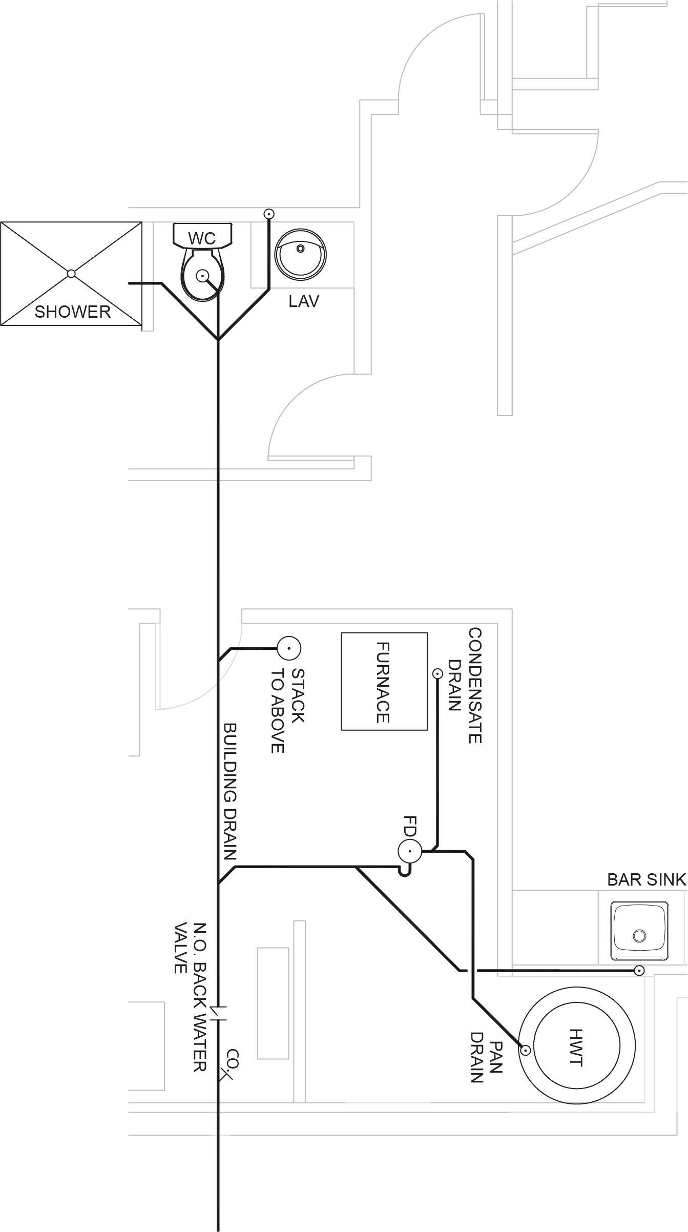
The plumbing plan is a two-dimensional plan view drawing showing the plumbing system. It is generated from the architectural floor plan showing the types and locations of the plumbing fixtures in the building. The plumbing plan describes the location, sizes, and types of all piping and fittings used in the system rough-in. The horizontal branches and fixture drains are drawn to scale, but due to the two-dimensional properties of the drawing, only the locations of all vertical pipes are shown.
Sketching a Plan View of a Residential DWV System
The first step in creating an orthographic plumbing plan is to determine the locations of any fixtures and stacks in the basement level. The stack locations will depend on the locations of the fixtures on the floor(s) above. The exact stack locations can be added later once the upper floor piping has been designed. It is very important to note where the sanitary sewer service enters the building. This will be the design starting point, working back toward the fixture locations.
You can then tie in all of the fixtures and stacks, including all required fittings, such as the building drain cleanout and a normally open back water valve.
The stacks, branches, and fixture drains in the vertical plane are represented by open circles with a dot in the centre, while horizontal branches and fixture drains are shown as they would appear from above.
Sizing of the DWV system should be based on minimum code requirements for the fixture unit load being served. Once the sizing is complete, the next step is to determine the fittings required for the under-slab rough-in.
The DWV system for the floors above must be drawn on a separate drawing sheet using the same procedure (Figure 20). The stacks are represented by open circles without a dot in the centre that show the stacks dropping vertically to the lower floor, while horizontal branches and fixture drains are shown as they would appear from above. Ensure that the location where the stacks drop to the basement is the same location where the stack rises up through the basement floor. This will eliminate the need for an offset to connect the stack sections.
Choosing a Scale
You may choose to draw the orthographic plumbing plan on the house plan, or you may want to use a separate sheet of paper. When you draw an orthographic plan or isometric sketch on a drawing sheet, you must use an appropriate scale to ensure that the amount of information you need fits on your page. When choosing a scale, it is important to consider the size of paper you wish to use. The best way to determine the proper scale is to divide the longest length of your project by the longest dimension of your drawing page.
For example, if the floor plan measures 50 ft (or 600 in.) in length and the drawing sheet is 12 in., the scale would be:
[latex]\color{blue}{600\text{ in.}\div12\text{ in.}=50}[/latex]
1:50 or approx. [latex]\tfrac{1}{4}[/latex] in. per foot
Sketching Residential Plumbing Groundwork Using Isometric Techniques
Isometric drawings are generated from the information found on the orthographic plan and elevation views when available. Unlike orthographic plumbing plans, isometrics allow the DWV system to be drawn in a manner by which the length, width, and height are shown in a single view. This allows for a more complete view of the groundwork system. Like the orthographic sketch, the isometric sketch is also drawn to scale so that the exact locations of fixtures and piping can be shown. Note that non-isometric lines, such as 45° elbows and Y-fitting branches, are not to scale. In this case, you must refer to an orthographic drawing for dimensions.
Usually, piping isometrics are drawn on sheets pre-printed with lines drawn vertically and at 30° to the horizontal (Figure 2). The symbols that represent fittings and valves are modified to adapt to the isometric grid. Isometrics are the most important drawings for mechanical contractors during the rough-in portion of a project.

As when creating an orthographic sketch, the first step in drawing an isometric sketch is to determine where the fixtures, stacks, and building sewer are to be located. This is an important step for laying out the groundwork and for deciding how to orient the sketch on the paper. The orientation on the drawing sheet is an important factor to consider because you want to avoid lines crossing one another or lines blocking the view of other piping or fittings.
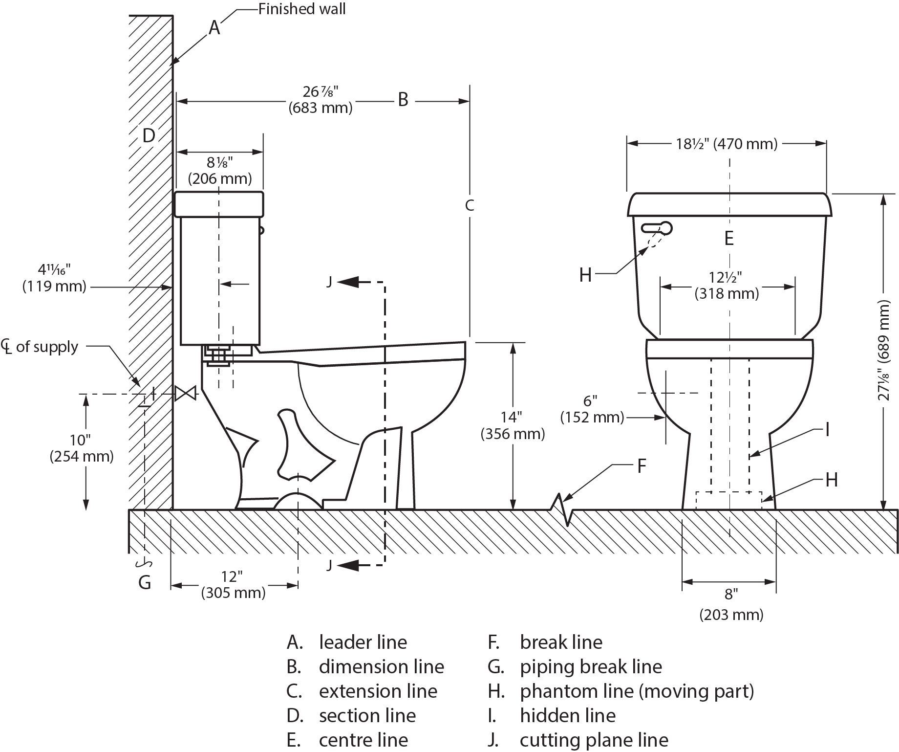
Fixture Specifications
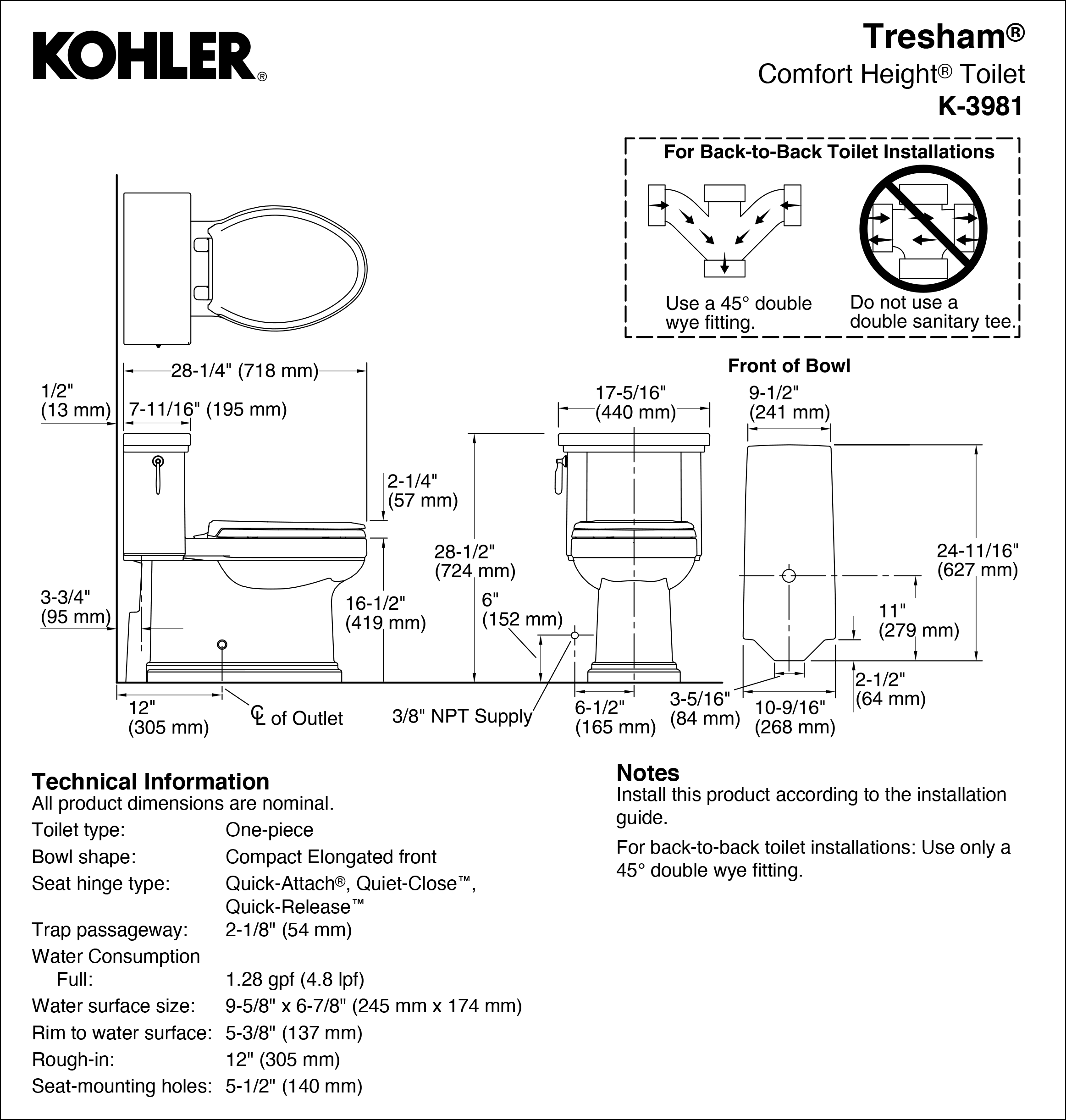
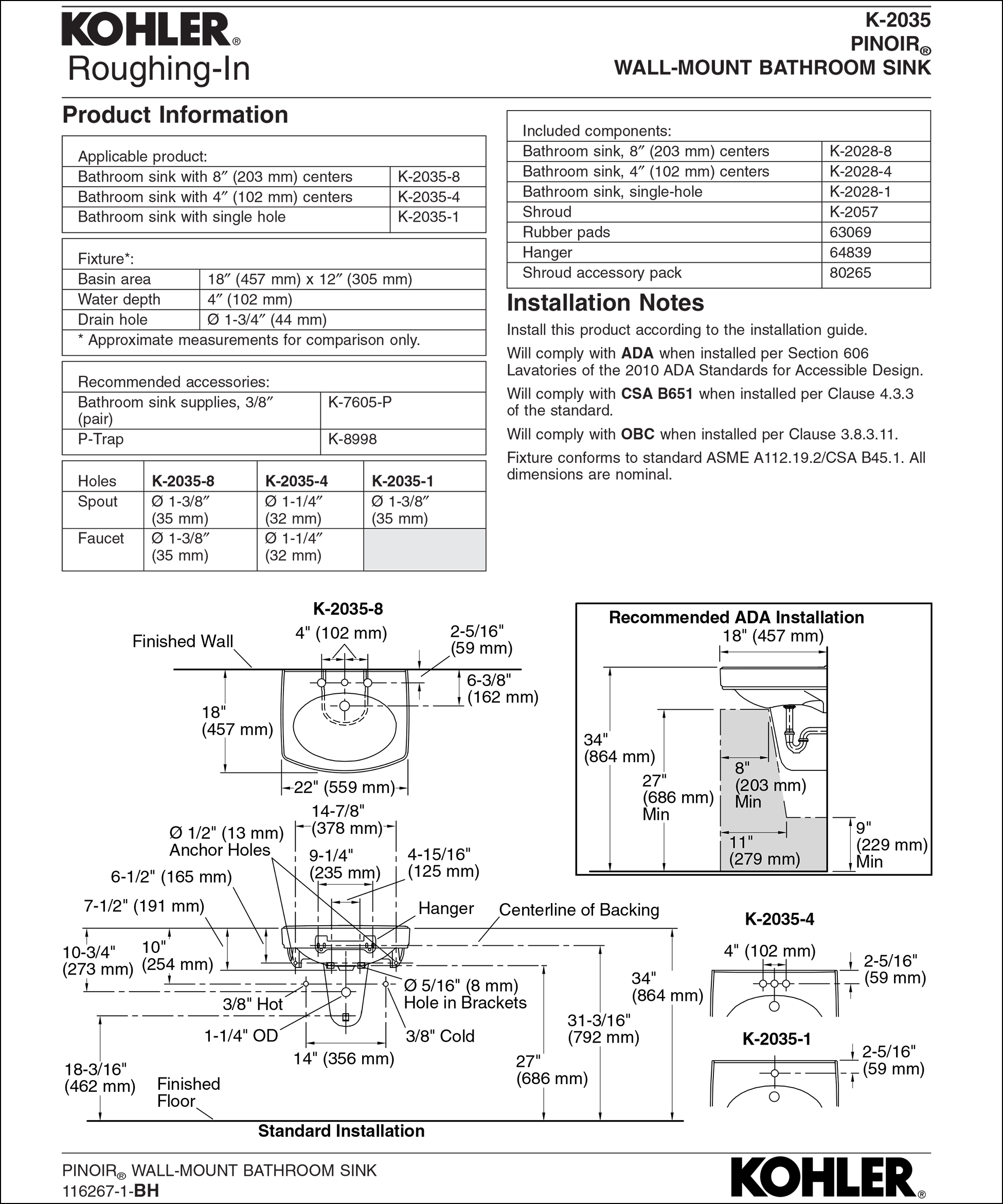
Once the fixture locations have been established on the drawing sheet, the next step is to determine the fixture manufacturer’s specifications to determine the associated rough-in dimensions for the drain and water lines. This fixture model is provided in the specifications for the project, while the dimension information is available from a rough-in manual or the company website in both imperial and metric measurements (Figures 3 and 4).
The information typically found in the manufacturer’s rough-in manual includes:
- Fixture dimensions
- Distance to the centre of the fixture’s drain from the finished wall
- Height of the drain and water line connections from the floor
- Centre-to-centre dimensions of faucets
- Support backing for wall-hung fixtures
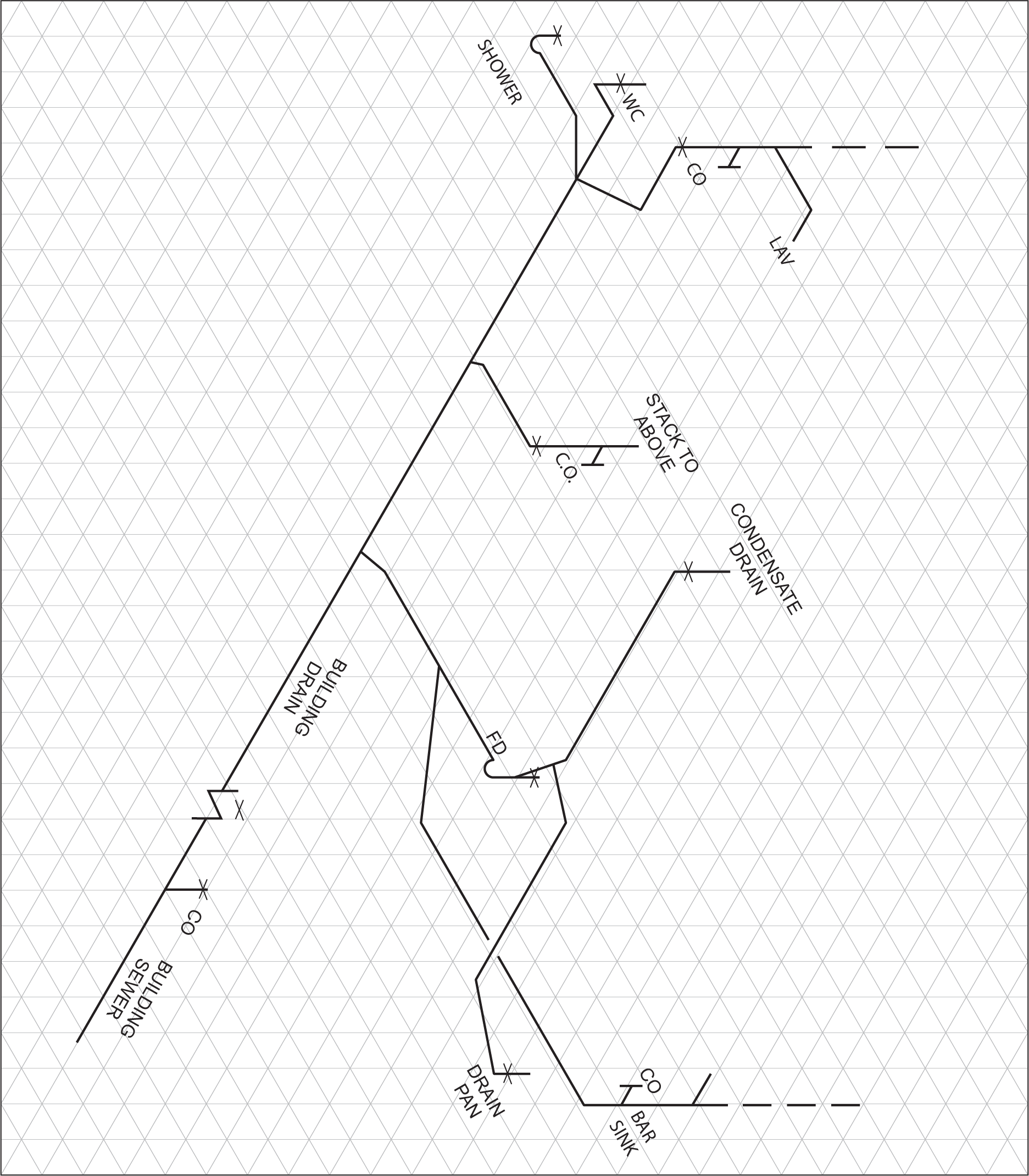
Plotting Fixtures
After you have obtained the rough-in dimensions for each fixture, you can begin to plot the location of the DWV slab penetration points on an isometric drawing. This would include the floor-mounted fixtures and any risers or waste stacks. These points should be marked with an isometric X on the drawing, as shown in Figure 5.
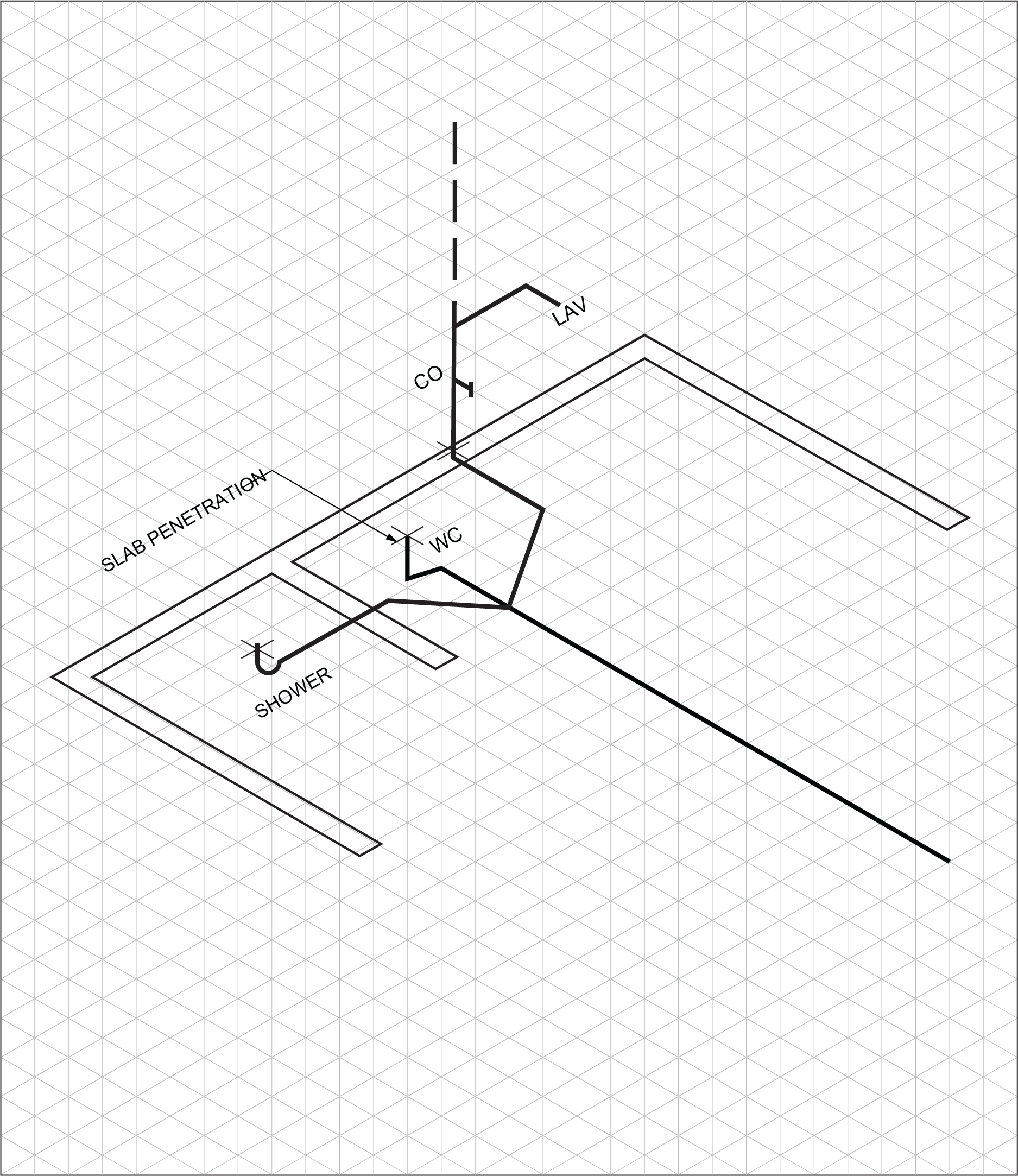
Once the slab penetration locations are plotted, it is time to connect them. Make sure that all connections are made to minimum code requirements. Take special care to use appropriate fittings for the layout with the cleanouts properly located and accessible for future use. When drawing the sketch, the plumbing vents should be indicated using dashed lines to differentiate them from the drains (Figure 6).
Upper Floors
As with groundwork, the DWV system drawn isometrically moving up through the structure provides a more complete three-dimensional view of the upper portion of the plumbing system (Figure 7). These sketches reveal connections to fixtures on upper floors, locations of stacks and vents within walls, and how the venting system terminates in open air.
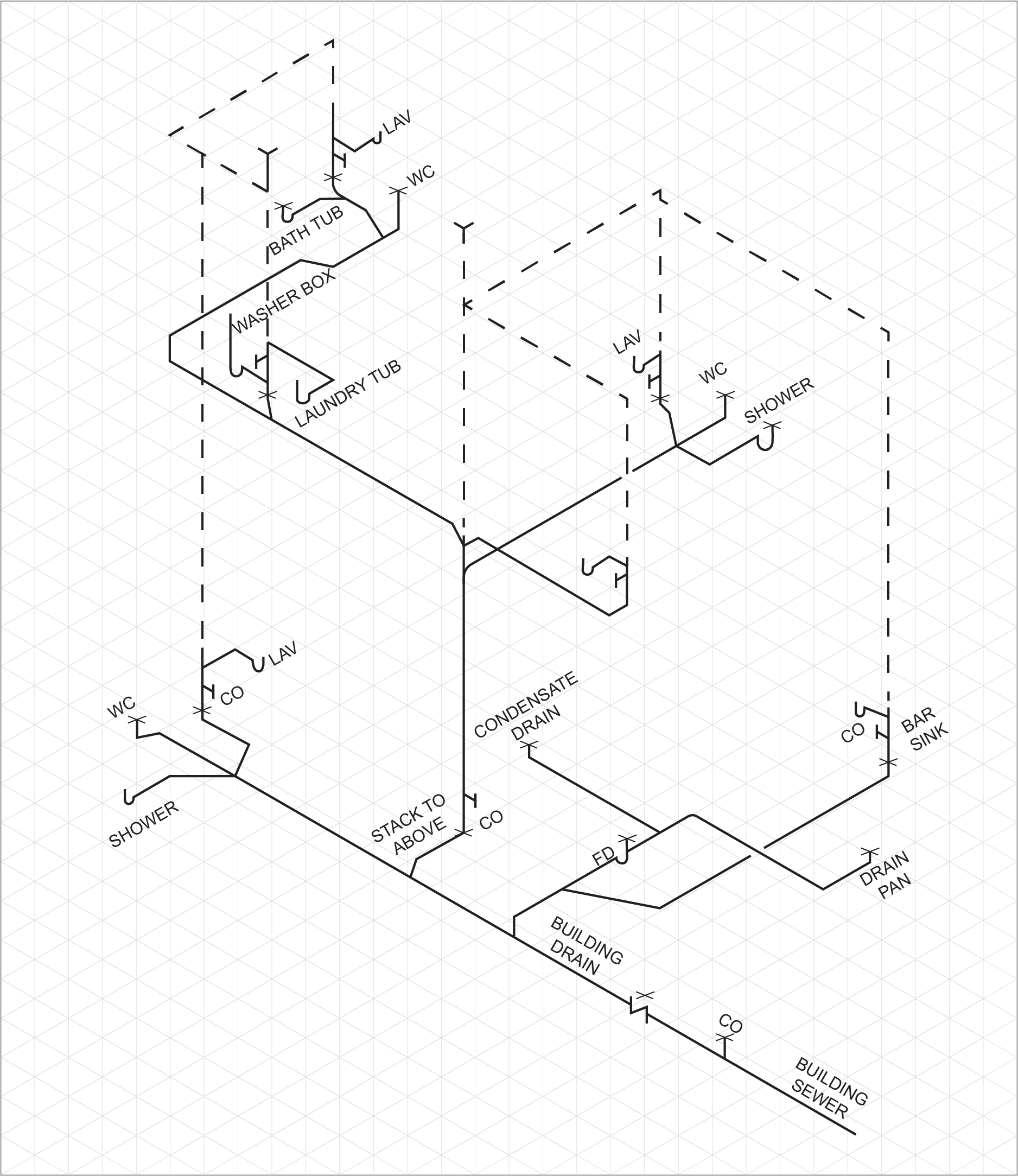
Vertical stacks, vents, and drainage branches are laid out in the same fashion as the groundwork plumbing. The floor penetrations are marked with an isometric X. The fixture connections to the DWV system must be installed to minimum code requirements.
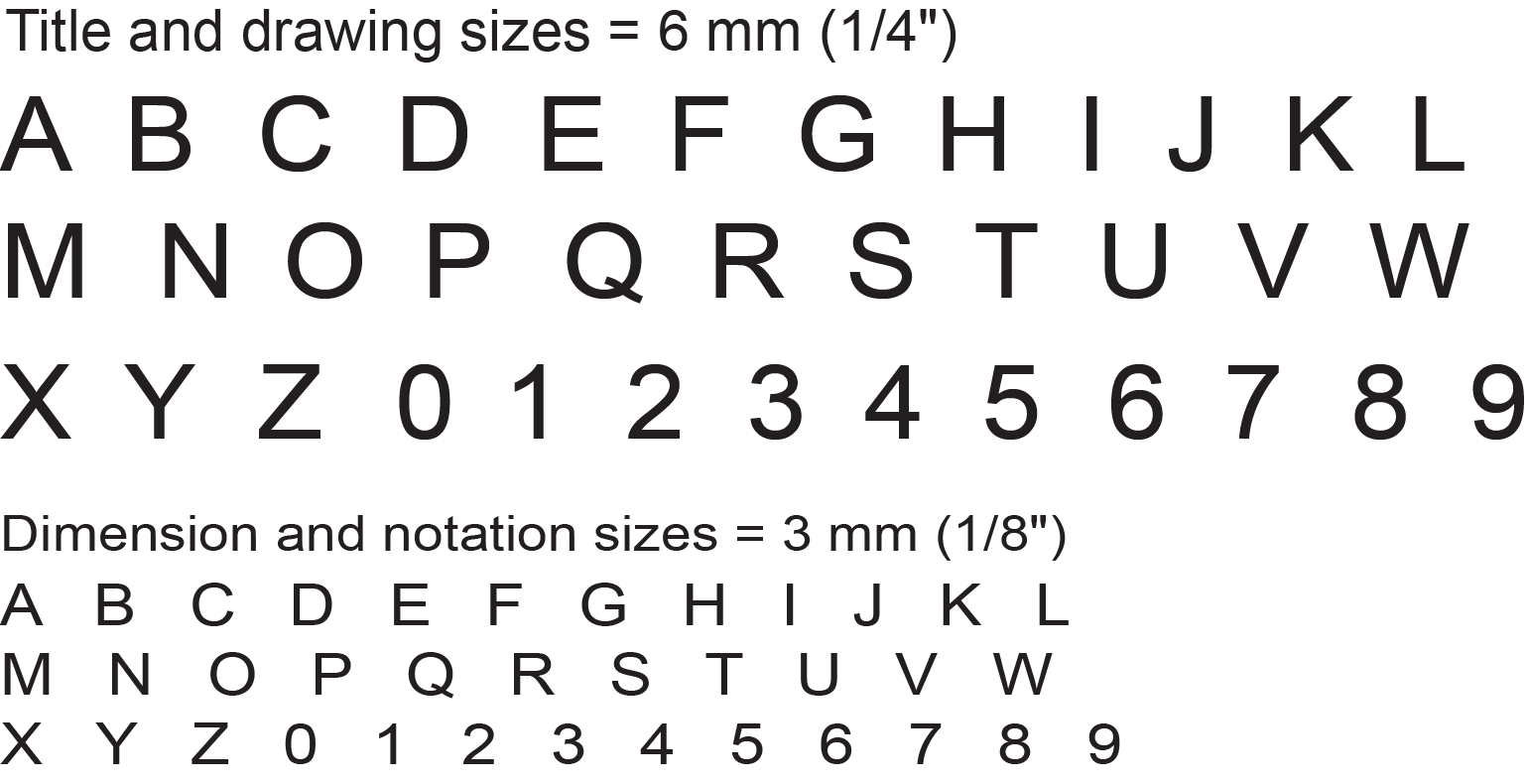
Letters and Numbers
All drawings require some form of lettering and numbers, and these are as important as the lines. Scribbled, smudged, or badly written letters and numbers can be impossible to read. This may lead to time-consuming and costly errors.
Remember these principles when lettering and numbering:
- They should be legible and clear — especially numbers, as they often have to be read on their own.
- They should be of a suitable size and not less than 3 mm tall. Title blocks and relative information are usually larger (see Figure 8).
- All letters are written in capital (uppercase) letters.
- Letters should be correctly spaced and positioned.
- Notes and captions should be placed so that they can be read in the same direction as in the title block. In other words, it should not be necessary to turn a drawing on its side to read the information.
- Notes should be grouped together and not spread over the drawing.
- Underlining is not recommended.
Line Type
Standard lines have been developed so that every drawing or sketch conveys the same meaning to everyone. In order to convey that meaning, the lines used in technical drawings have both a definite pattern and a definite thickness (Figure 9). Some lines are complete and others are broken. Some lines are thick and others are thin.

Study the line thicknesses (line weights) shown in Figure 10 and practise making them. Use a sharp pencil when you draw, and try to maintain an even, consistent pressure to make it easier for you to produce acceptable lines.
In computer drafting, the line shape remains the same as in manually created drawings, but line thickness may not vary. Some lines, such as centrelines, may not cross in the same manner as in a manual drawing. For most computer drafting, line thickness is not important.
Figure 10 shows the nature of each line and explains how they are used in a technical drawing. You should be able to identify each line by name and describe its application.
Information to be Contained in Drawings
Plan view DWV drawings and isometric DWV drawings are drawn to a specific scale and should show as much of the drainage and venting for a plumbing system as the view allows. Information such as rough-in heights, connection points to fixtures, floor penetrations, vent types, and vent locations should all be shown to enable the drawing to be as clear as possible while still fitting all information on the page.
Plumbing DWV drawings (isometric and orthographic plan) are really installation drawings. An installation drawing provides information for the proper positioning and installation of plumbing systems relative to the supporting structure and adjacent equipment, as applicable. This information may include:
- Dimensional data
- Piping configurations
- Piping materials
- Pipe sizes
- Fixture types
- General configuration information for the installation site
Dimensioning
Once the plan or isometric views of a piping assembly are created, they are not useful until they are completely and properly dimensioned. Dimensions show the length and size of DWV piping, as well as specific details that will determine how specific equipment is installed.
Dimensioning a drawing can be broken down into two steps:
- Decide which dimensions are required.
- Decide the best place on the drawing to place the selected dimensions.
A drawing that does not have all the required dimensions is said to be under-specified. This means that the person reading the drawing and installing the piping system does not have enough information to reproduce it. A drawing can also contain too many dimensions and, in that case, would be over-specified. Dimensions should NOT be duplicated, nor should the same information be given in two different ways.
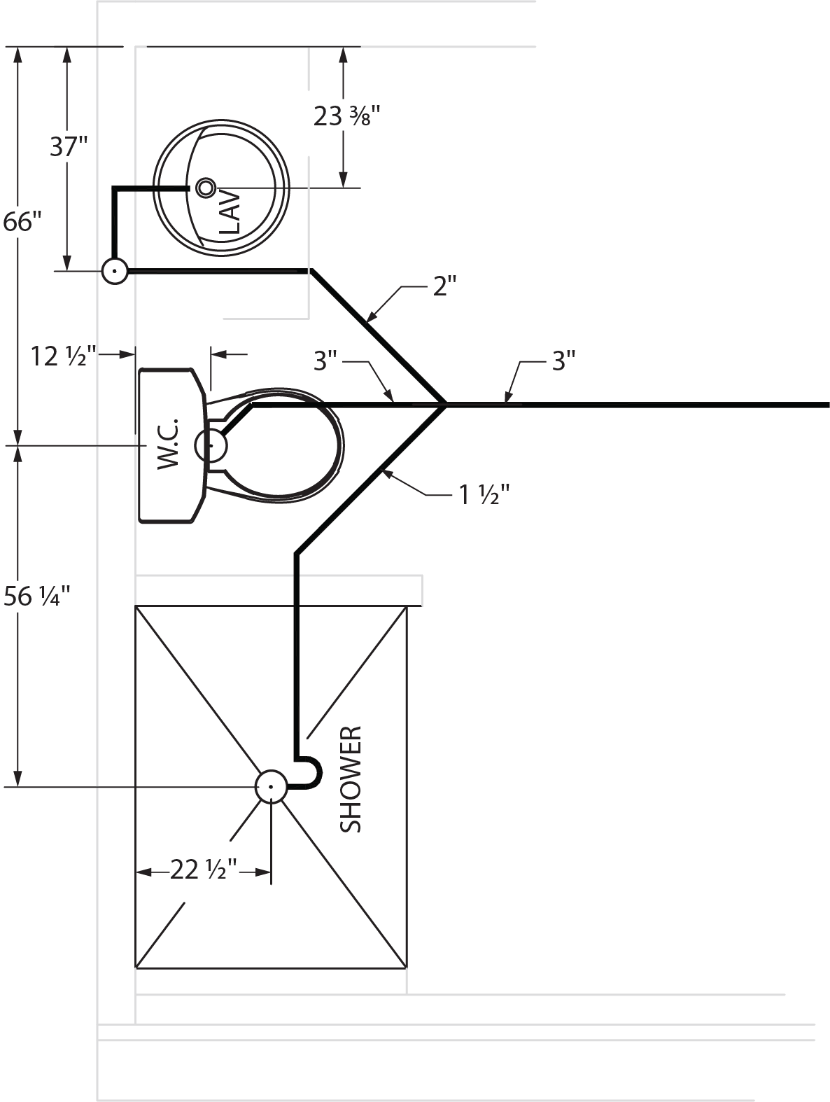
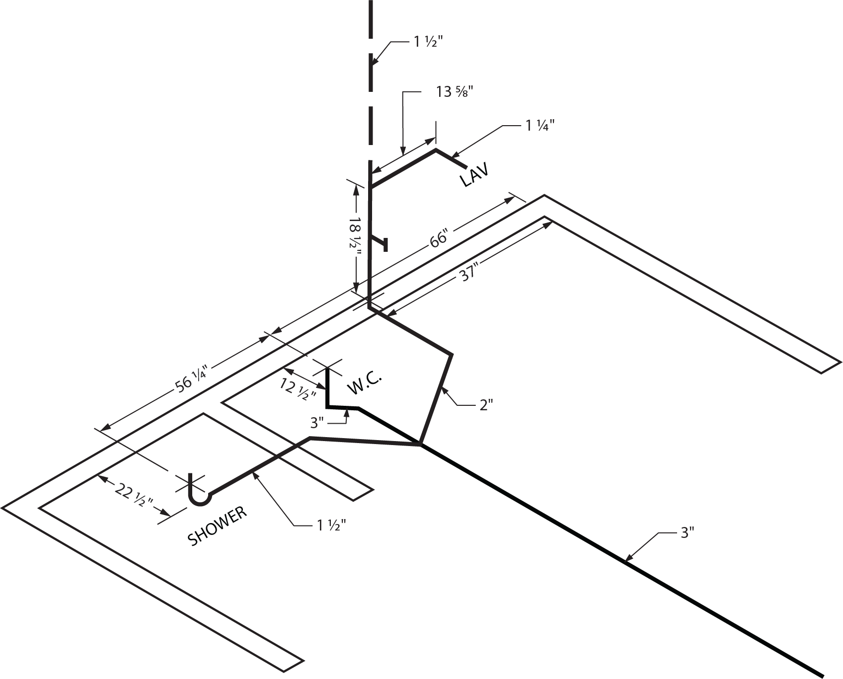
Figures 11 and 12 show plan and isometric views of the same three-piece bathroom group. Note that the three-dimensional isometric drawing has the advantage of being able to show all of the information needed to install the rough-in. The isometric drawing is dimensioned with extension and dimension lines like a two-dimensional drawing. The extension lines extend from the drawing so the dimension lines are parallel to the object line.
Pipe Sizing
Sizing of the DWV system should be based on minimum code requirements. The drainage piping is only dependent on the connected load, while the size of vent piping is determined from its length and the total number of fixture units connected. Since the isometric drawing is to scale, the pipe lengths can be measured accurately with a scale rule.
Once every line is correctly sized, the next step is to determine the fittings required for the installation and the amount of piping required.
 Self-Test D-2.3: Creating Plans and Isometric Drawings of DWV Systems
Complete Self-Test D-2.3 and check your answers.
If you are using a printed copy, please find Self-Test D-2.3 and Answer Key at the end of this section. If you prefer, you can scan the QR code with your digital device to go directly to the interactive Self-Test.

References
Skilled Trades BC. (2021). Book 2: Install fixtures and appliances, install sanitary and storm drainage systems. Plumber apprenticeship program level 2 book 2 (Harmonized). Crown Publications: King’s Printer for British Columbia.
Trades Training BC. (2021). D-2: Plan DWV systems. In: Plumber Apprenticeship Program: Level 2. Industry Training Authority, BC.
Media Attributions
All figures are used with permission from Skilled Trades BC (2021) unless otherwise noted.
- Figure 3 Manufacturer’s rough-in specification sheet for a residential toilet is courtesy of Kohler Co. and is used with permission. All rights reserved.
- Figure 4 Manufacturer’s rough-in specification sheet for a wall-hung basin is courtesy of Kohler Co. and is used with permission. All rights reserved.
3-dimensional (3D) pictures that show how pipes in a building connect and work together. They help plumbers see where drain, waste, and vent pipes go and what size they should be. These drawings make it easier to plan and install plumbing systems correctly, whether in homes or larger buildings. (Section D-2.3)
A two-dimensional plan view drawing showing the plumbing system. It is generated from the architectural floor plan showing the types and locations of the plumbing fixtures in the building. The plumbing plan describes the location, sizes, and types of all piping and fittings used in the system rough-in. The horizontal branches and fixture drains are drawn to scale, but due to the two-dimensional properties of the drawing, only the locations of all vertical pipes are shown. (Section D-2.3)
A 2D drawing that shows different views (top, front, side) of an object. (Section D-2.3)
The location where a pipe passes through a floor or wall. (Section D-2.3)
The process of adding measurements to a drawing. (Section D-2.3)
