D-1.9 Sizing Stack Vents, Vent Stacks, and Headers
The upper end of every stack becomes a stack vent above the highest fixture connection. The stack vent can extend individually to open air or connect into another stack vent or vent stack, becoming a vent header, and then extend to open air. It is important to note that the stack below the stack vent connection cannot be smaller than the size of the stack vent.
Sizing Stack Vents
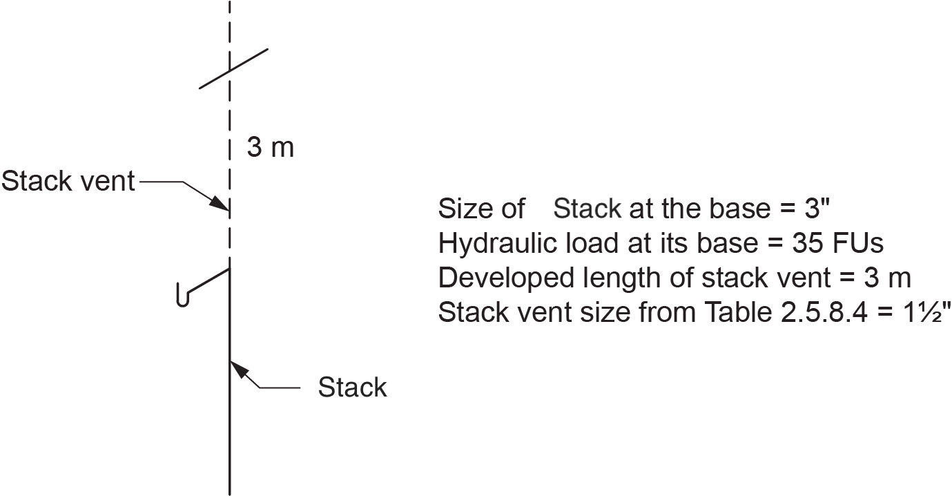
Stack vents are sized using Table 2.5.8.4. in the NPC (2020, B 2-46; refer to Figure 1 below). When using this table to obtain the size of the stack vent, there are three things to consider:
- The size of the stack served by the stack vent. Because a stack may become larger as the loads from floors are drained to it, the size at the base of the stack is the size to consider. Do not use the size of the stack at the top where the stack vent connects.
- The hydraulic load (FU load) at the base of the stack served by the stack vent.
- The developed length of the stack vent. This is measured from the lower end of the stack vent through to open air, even if a vent header is installed.

The NPC (2020) requires that the minimum size of a stack vent not be smaller than one-half the size of the stack at its base and never be smaller than permitted by Table 2.5.7.1.
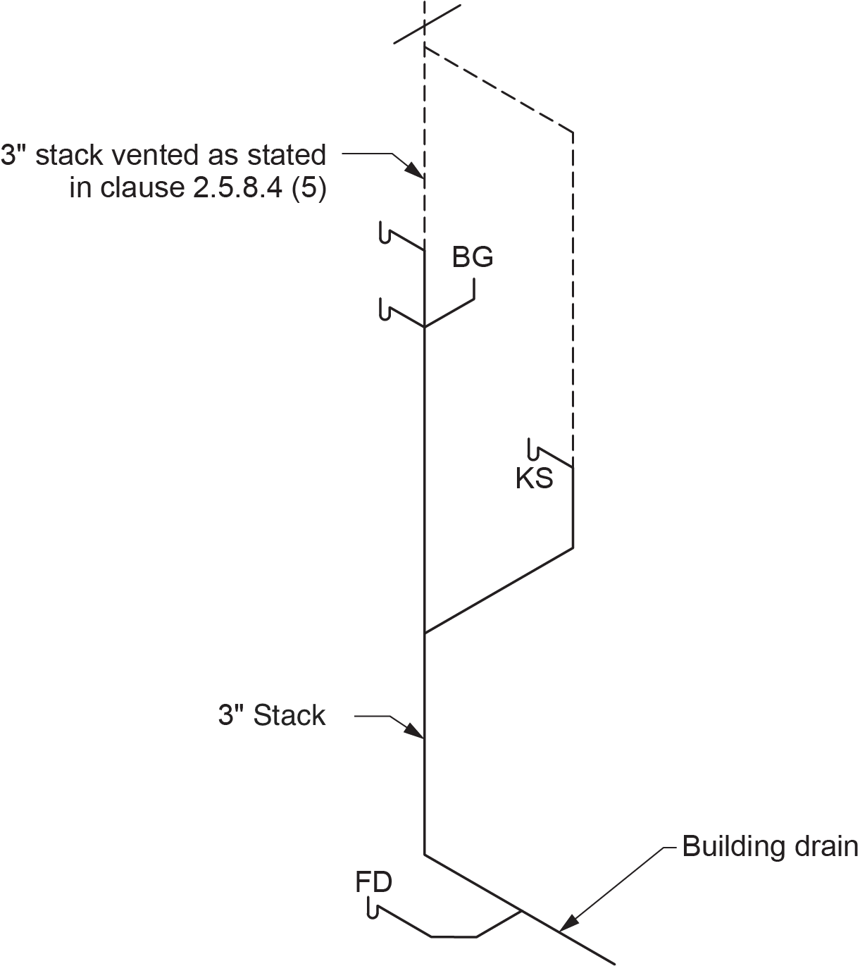
Clause 2.5.8.4.(5) states that “Every building drain shall be provided with at least one vent that is not less than 3 in. in size.” This requirement would overrule Table 2.5.8.4. if there is only one 3 in. stack in a building, such as in a single-family dwelling. If a building has more than one 3 or 4 in. stack, then at least one of the stack vents must be at least 3 in. through to open air (Figure 2).
Sizing Vent Stacks
A vent stack is a vent installed in conjunction with a stack used to limit the pressure differential created between the drainage and venting systems. The NPC states that any stack that receives discharge from more than four storeys requires a vent stack. However, this rule does not apply to multi-storey wet vents sized to provide ample air circulation within the wet-vented stack.
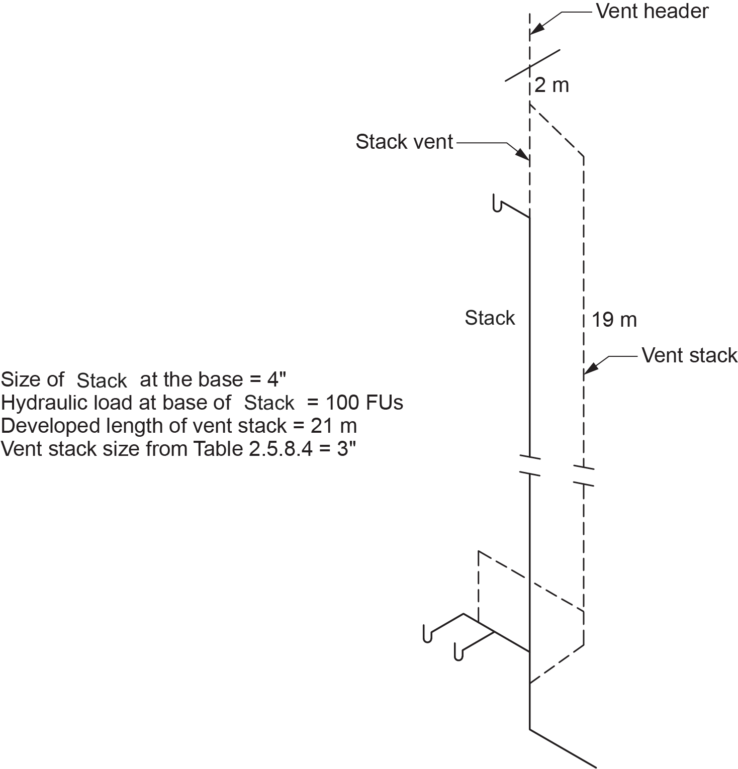
Vent stacks are also sized using Table 2.5.8.4. in the NPC (2020, B 2-46). When using this table to obtain the size of the vent stack (Figure 3), there are three things to consider:
- The size of the stack at the base served by the vent stack. This would be the location where the vent stack connects to the stack below the lowest fixture connection to the stack.
- The hydraulic load (FU load) at the base of the stack served by the vent stack plus any additional vent loads connected to the vent stack.
- The developed length of the vent stack. This is measured from the lower end of the vent stack through to open air, even if a vent header is installed.

The NPC requires that the minimum size of a vent stack not be smaller than one-half the size of the stack at its base and never be smaller than permitted by Table 2.5.7.1.
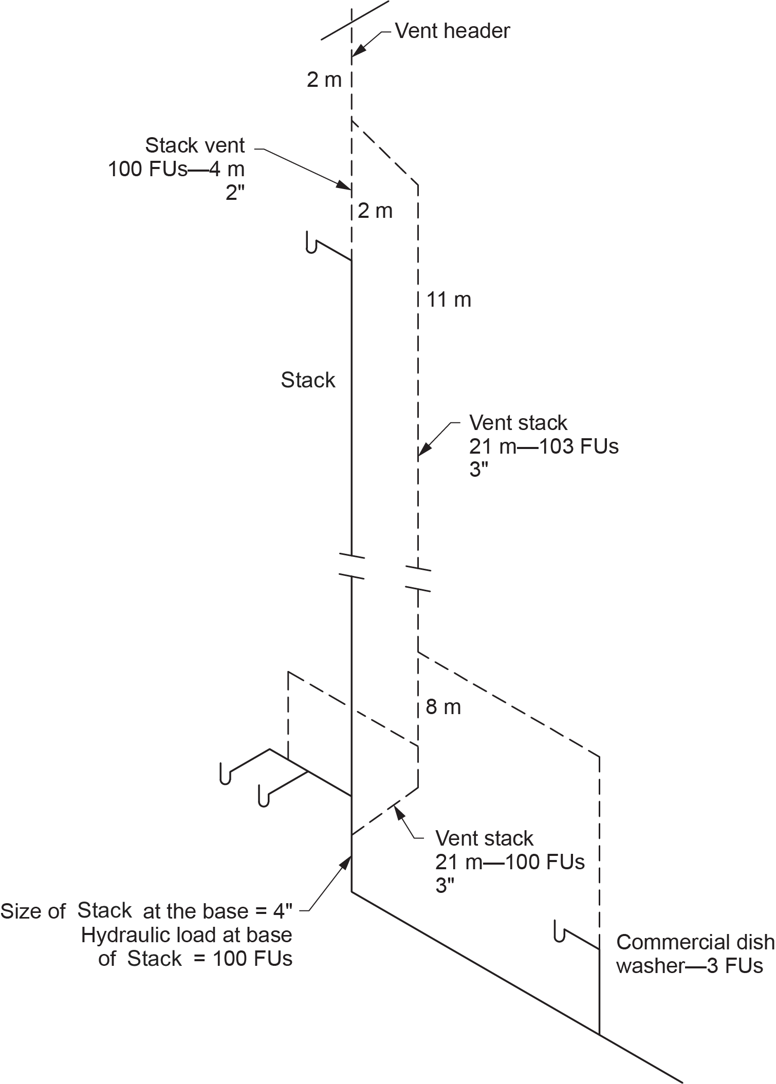
There are often instances when fixtures do not drain to a stack served by a vent stack, but the vents from these fixtures do connect to the vent stack. In such cases, the hydraulic load on the vent stack will increase from that point of connection as the additional venting loads are introduced to the vent stack (Figure 4).
Venting from similar scenarios, where additional fixtures vent loads may tie into a stack vent, are dealt with in the same manner.
Fixtures Connecting to the Base of Vent Stacks
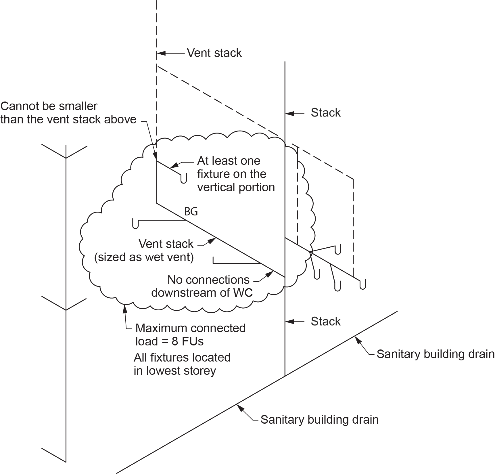
Clause 2.5.4.2.(4) of the NPC allows fixtures to connect to a vent stack (Figure 5), provided that the following conditions are met:
- The total hydraulic load of the connected fixtures does not exceed 8 FUs.
- At least one fixture is connected to a vertical portion of the vent stack and is upstream of any other fixtures.
- No other fixture is connected downstream of a water closet.
- All fixtures are located in the lowest storey served by the vent stack.
- The section of the vent pipe that acts as a wet vent conforms to the requirements regarding wet vents.
- The wet-vented portion described above cannot be smaller than the size of the vent stack above the wet vent.
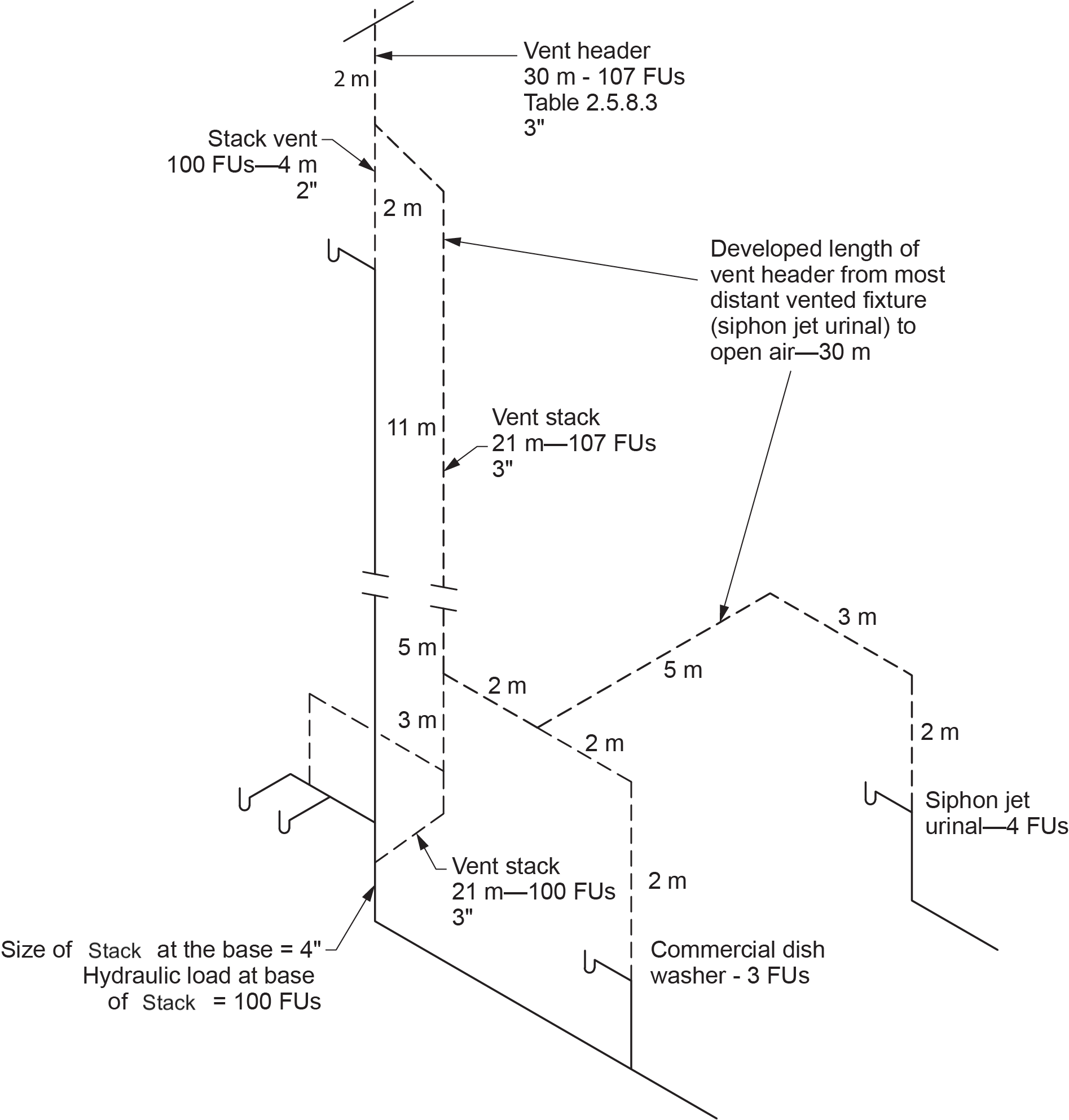
Size Vent Header
Vent headers are sized using Table 2.5.8.3. in the NPC (Figure 6). When using this table, you must consider two things:
- The total number of fixture units being vented by the vent header
- The total developed length of the vent header, which is measured from the furthest vented fixture through to open air
Sizing Miscellaneous Vent Pipes
A number of other miscellaneous special vents do not have an additional hydraulic venting load but may be required to provide proper air circulation within the DWV systems. These can include:
- Sump vents
- Yoke vents
- Offset relief vents
Sanitary Sewage Sumps
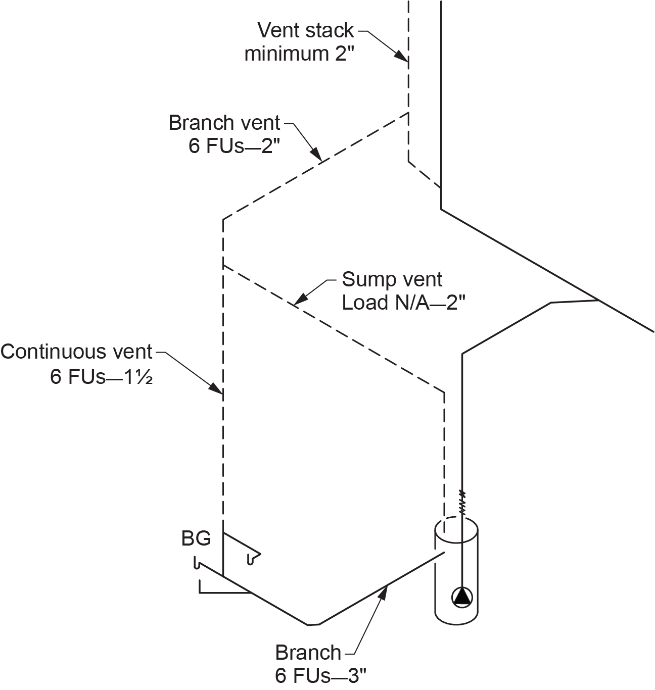
Every sump or tank that receives sanitary sewage shall be provided with a vent pipe connected to the top of the sump or tank. The lower end of the vent serving a sanitary sewage sump or tank connects to the lid or the upper interior side extending upward to any other part of the venting system. The size of the vent is found in Clause 2.5.7.7.:
The minimum size of the vent pipe for a sanitary sewage sump or tank or a dilution tank shall be one size smaller than the size of the largest branch or fixture drain draining to the sump or tank. The size shall be not less than 50 mm (2 in.) and need not be greater than 100 mm (4 in.).
In other words, a 2 in. vent is the minimum size for a sump vent if it receives waste from a 3 in. drain, a 3 in. vent is the minimum size if it receives waste from a 4 in. drain, and so on.
Unlike fixtures that drain to the sump, the sump vent does not have a hydraulic load associated with it. When it connects to a branch vent or vent stack, it does not increase the load at the connection point. The branch vent or vent stack may have to be increased in size above the connection point because Clause 2.5.7.2.(1) requires that the size of a branch vent or vent stack be not less than the size of the vent pipe to which it is connected (Figure 7).
Macerating Toilet Systems
The size of every vent pipe for a macerating toilet system with a sump or tank shall be not less than 38 mm ([latex]1\tfrac{1}{2}[/latex] in.).
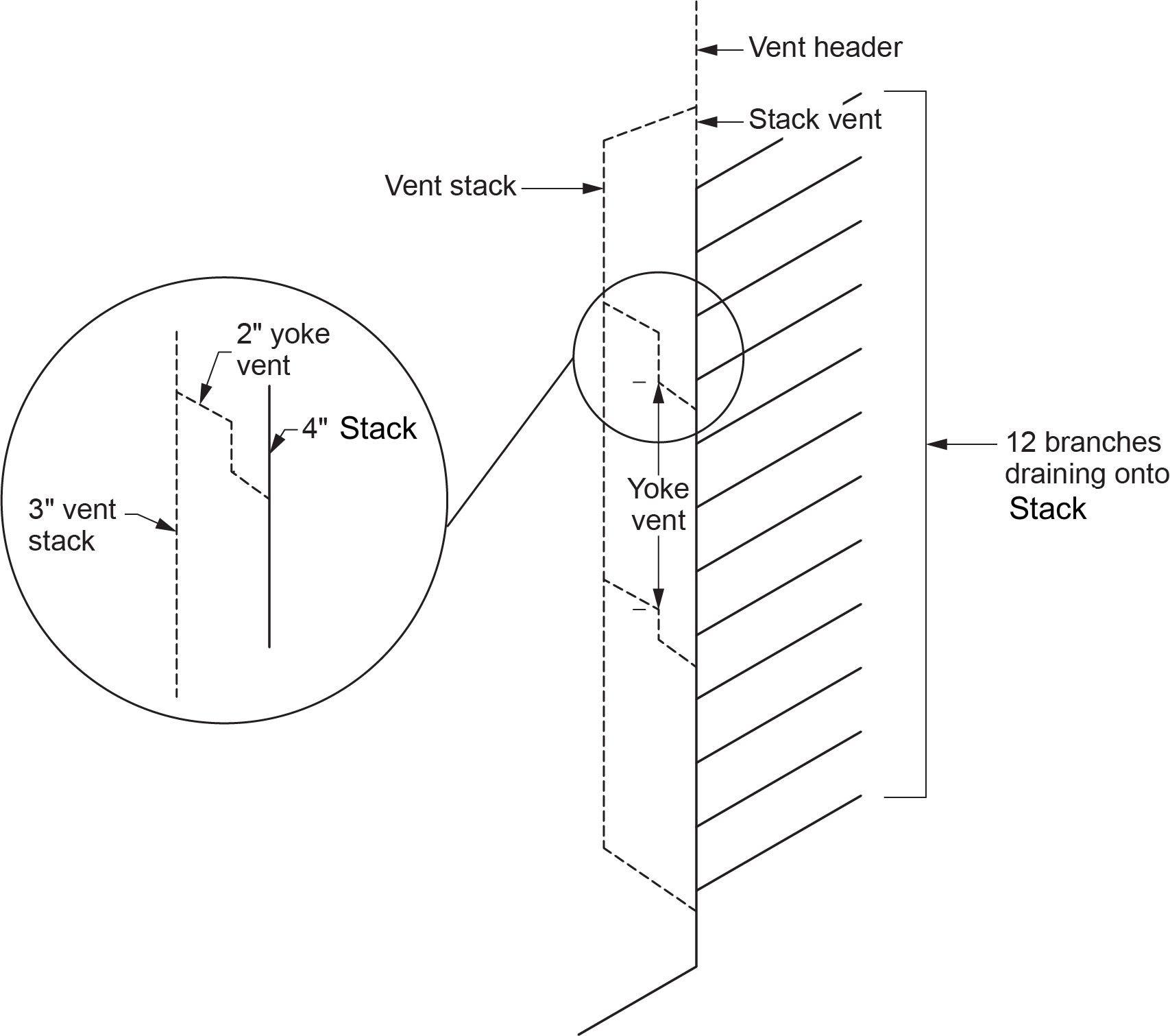
Yoke Vents
Additional vents are sometimes required on buildings more than 11 storeys tall to minimize the effect of pressure changes in the DWV system. The need for these vents can be eliminated by interconnecting the stack with the vent stack in each storey where the fixtures are located. This can be done using a vent pipe equal in size to the branch or fixture drain or 50 mm (2 in.) in size, whichever is smaller.
- When required, yoke vents are installed on every fifth storey (counting from the top down) and immediately above each offset or double offset.
- The lower end is connected to the stack by a drainage fitting at or immediately below the last connected fixture on the lower floor of the five-storey section.
- Yoke vents are sized by the pipes to which they are connected and are allowed to be one pipe size smaller than the smallest pipe to which they are connected (Figure 8).
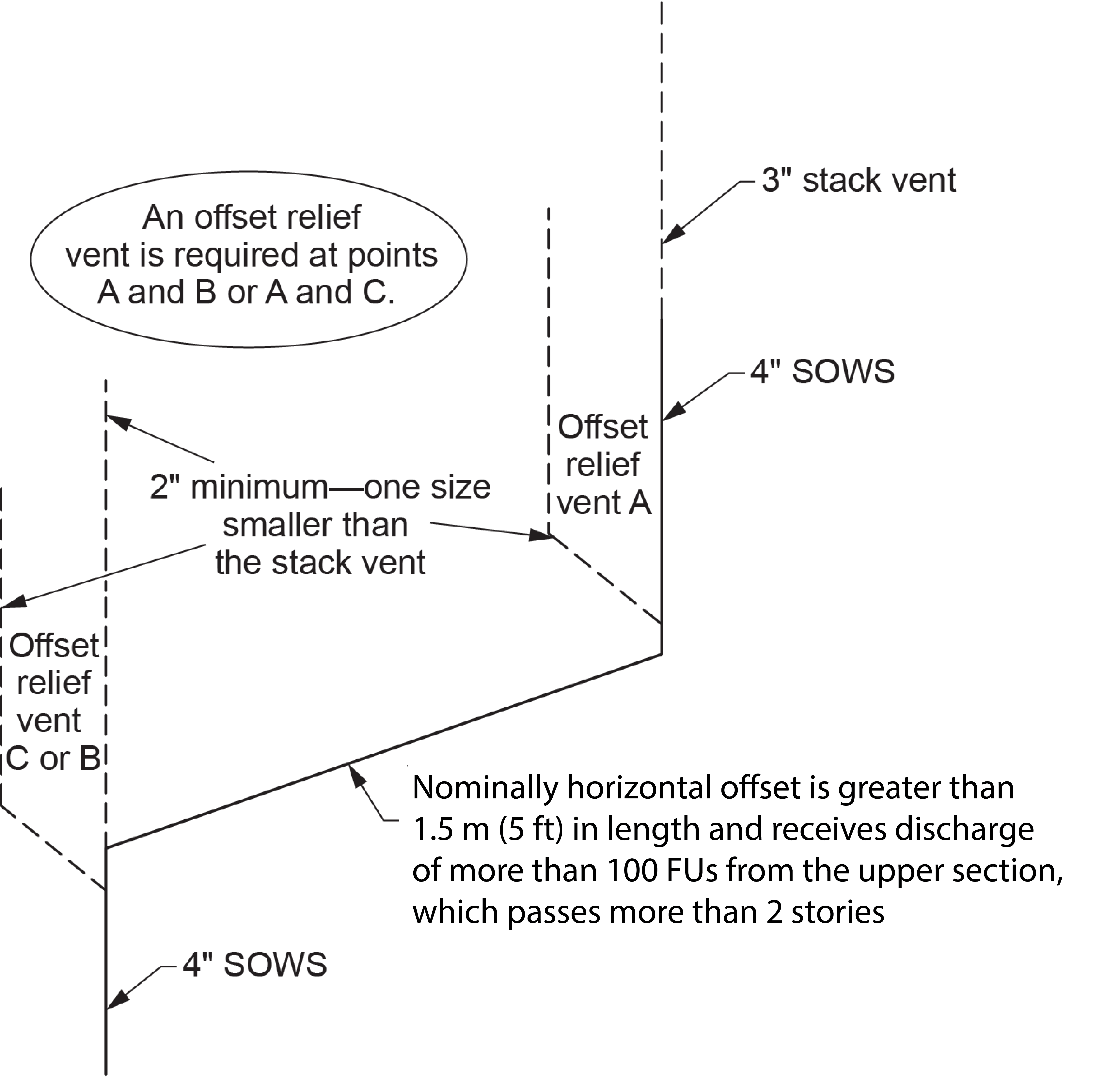
Offset Relief Vents
An offset relief vent provides additional air circulation to a stack with a nominally horizontal offset of more than 1.5 m (60 in.) long and where the upper portion of the stack passes through three or more storeys and has more than 100 fixture units on it.
- The connection of the offset relief vent is made at the lowest end of the upper stack, after the last sanitary drainage pipe connection, and the upper end of the lower stack higher than any drain connections.
- The minimum size of an offset relief vent is permitted to be one size smaller than the size of the stack vent serving the stack (Figure 9).
Putting it All Together
In the previous sections, you were asked to identify and determine hydraulic loads and size individual sections of a DWV system. In the following self-test, you will be asked to use these skills to size “whole building” DWV systems. The ability to design and size a total DWV system to minimum code standards is essential to eliminate on-site code violations as an apprentice or journeyperson.
At first glance, the following drawings may look complicated, but in reality, they are just groups of fixtures and connected piping that you are familiar with. By following a simple procedure and practice, you will find that the sizing exercises become easier. Here are some hints to help you establish a sizing procedure:
- If a group of fixtures falls under the definition of a “bathroom group,” the hydraulic load will either be 6 or 8 FUs, depending on the flushing mechanism of the water closet. Look for bathroom groups, circle them, and jot down the FU load.
- If an existing bathroom group has additional fixtures, such as an additional lavatory, then the hydraulic load for the total group will be a bathroom group plus the load of the additional fixture(s).
- When determining the hydraulic load on any part of the drainage section of the DWV system, it is best to start at the highest fixture and work your way down the drawing toward the building sewer. Because the drainage load is additive, it will be easier to determine the hydraulic load on any section.
- When determining the hydraulic load on any part of the venting section of the DWV system, it is best to start at the lowest fixture and work your way up the drawing to open air. As with the drainage section, the venting load is also additive. This will lessen the possibility of errors and omissions.
- Ensure that the proper sizing table is being utilized for the piping based on the definition of the pipe in question.
- Focus on the location of water closets, remembering that the minimum size of drainage piping downstream will be 3 in. and the minimum size of any venting from one will be 1.5 in.
 Self-Test D-1.9: Sizing Stack Vents, Vent Stacks, and Headers
Complete Self-Test D-1.9 and check your answers.
If you are using a printed copy, please find Self-Test D-1.9 and Answer Key at the end of this section. If you prefer, you can scan the QR code with your digital device to go directly to the interactive Self-Test.

References
National Research Council of Canada. (2020). National plumbing code of Canada 2020. Canadian Commission on Building and Fire Codes. https://nrc-publications.canada.ca/eng/view/ft/?id=6e7cabf5-d83e-4efd-9a1c-6515fc7cdc71
Skilled Trades BC. (2021). Book 2: Install fixtures and appliances, install sanitary and storm drainage systems. Plumber apprenticeship program level 2 book 2 (Harmonized). Crown Publications: King’s Printer for British Columbia.
Trades Training BC. (2021). D-1: Install sanitary drain, water and vent systems. In: Plumber Apprenticeship Program: Level 2. Industry Training Authority, BC.
Media Attributions
All figures are used with permission from Skilled Trades BC (2021) unless otherwise noted.
A vertical sanitary drainage pipe that passes through one or more storeys and includes any offset in the stack. Previously referred to as a soil-or-waste stack or SOWS. (Section D-1.2; Section D-2.3)
A pit or basin that collects and temporarily holds wastewater before it is pumped to a sewer system or treatment facility, commonly used in low-lying areas where gravity drainage is not possible. (Section D-1.9)
A type of plumbing system that uses a grinding or chopping mechanism to break down waste and toilet paper into a fine slurry before pumping it to the main sewer or septic line. It is commonly used in locations where traditional gravity drainage is not possible, such as basements or areas far from the main waste pipe. (Section D-1.9)
