D-1.8 Sizing Branch and Circuit Vents
Although branch and circuit vents are very different types of vents, they share some common sizing characteristics and have, therefore, been grouped together in this chapter.
Branch Vents
A branch vent is sized according to Table 2.5.8.3 (NPC, 2020, B 2-45). When using this table, you need to know the developed length of the branch vent and the hydraulic load (FUs) it serves at any given point.
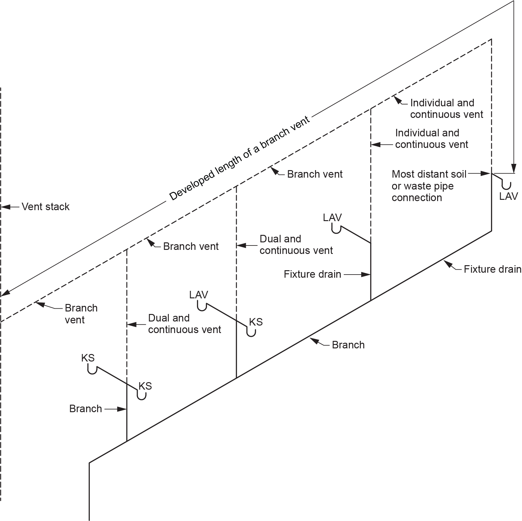
The length to consider when sizing a branch vent is from the most distant sanitary drainage pipe connection to the point where it ties into a stack vent, vent stack, or vent header or where it continues as a branch vent to outside air (Figure 1).
The load to consider when sizing a branch vent is the sum of the FU loads for the fixtures it serves — in other words, the number of fixture units on the sanitary drainage pipes that it provides air for. As the fixtures are added to a branch vent, the load increases (Figure 2).
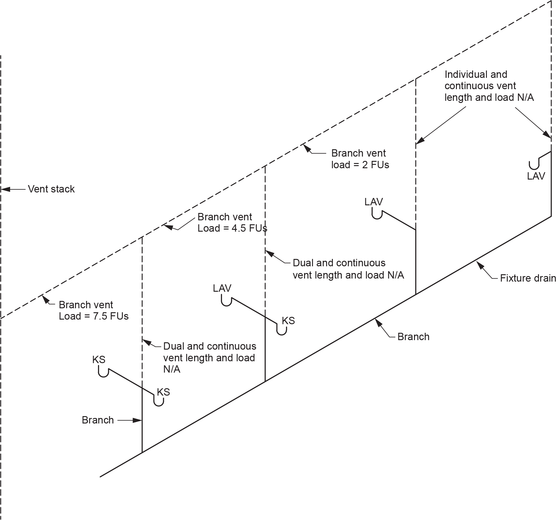
Branch vents will increase in size as more vents are connected to them (provided Table 2.5.8.3. dictates) but will never be smaller than permitted by Table 2.5.7.1. and any vent connected to it.
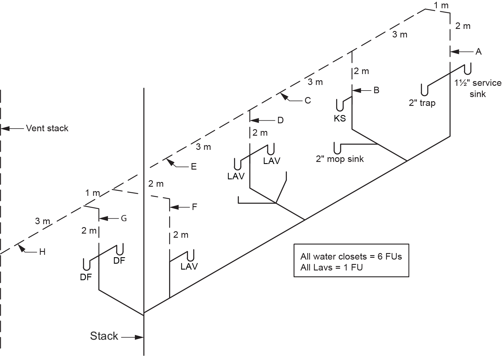
The following example shows how the developed length of the branch vents remains the same (from the most distant sanitary drainage pipe connection) but the loads are additive as the other Category 1 vents join the branch vent (Figure 3 and Table 1).
| Label | Name | Length (m) | Load (FU) | Size (in.) | Notes |
|---|---|---|---|---|---|
| A | Dual and continuous vent | N/A | N/A | 1.5 | Length and load N/A. Vent size from Table 2.5.7.1. using largest trap served |
| B | Continuous vent | 12 | 3.5 | 1.5 | Vent size from Table 2.5.8.3. Length from the connection of KS to the vent stack. Load is total of KS and mop sink |
| C | Branch vent | 16 | 8 | 1.5 | Vent size from Table 2.5.8.3. Length from the furthest sanitary drainage pipe connection to the vent stack. Load is total of fixtures served at that point |
| D | Continuous vent | 9 | 14 | 1.5 | Vent size from Table 2.5.8.3. Length from the connection of lavs to the vent stack. Load is total of lavs and WCs |
| E | Branch vent | 16 | 22 | 2 | Vent size from Table 2.5.8.3. Length from the furthest sanitary drainage pipe connection to the vent stack. Load is total of fixtures served at that point |
| F | Individual and continuous vent | N/A | N/A | 1.25 | Length and load N/A. Vent size from Table 2.5.7.1. using trap size served |
| G | Dual and continuous vent | N/A | N/A | 1.25 | Length and load N/A. Vent size from Table 2.5.7.1. using largest trap served |
| H | Branch vent | 16 | 24 | 2 | Vent size from Table 2.5.8.3. Length from the furthest sanitary drainage pipe connection to the vent stack. Load is total of fixtures served at that point |
Circuit Vents
Circuit venting is a form of group venting sometimes confused with wet venting. Instead of using the core of air in a vertical pipe, circuit venting uses the top of a horizontal drainage pipe to vent the fixtures connecting to the horizontal branch. The drainage section is not sized as a wet vent but as a branch from Table 2.4.10.6.-B (NPC, 2020, B 2-35).
To size the circuit vent, you must use Table 2.5.8.3. in the NPC 2020 code book.

Note: As with any vent, the circuit vent can never be smaller than permitted by Table 2.5.7.1. For example, if the circuit vent serves a water closet, Table 2.5.8.3. may permit a 1.25 in. vent. Table 2.5.7.1. overrides this value, as a 1.25 in. vent can only serve 1.25 in. and 1.5 in. traps.
Using Table 2.5.8.3. requires the following information:
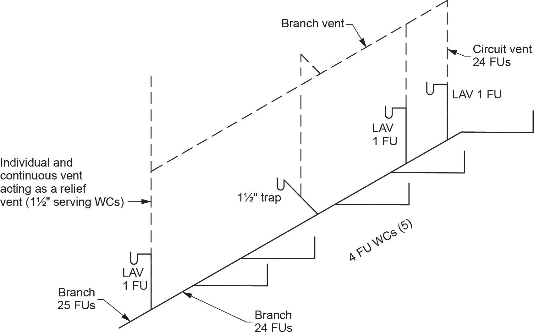
- The hydraulic load served by the circuit vent — The hydraulic load to consider is the total number of circuit-vented fixtures, not including the load of any fixtures that may be connected to the required relief vent. The hydraulic load is most often identical to the branch immediately upstream of the relief vent connection.
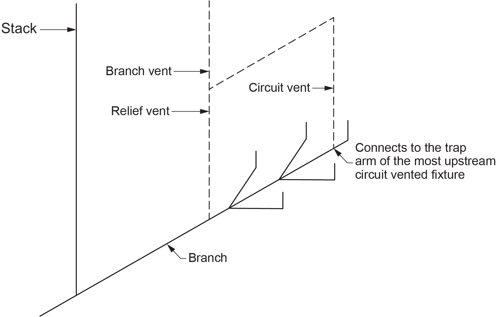
- The developed length of the circuit vent — The length to consider is from its lower end — where it connects to the trap arm of the furthest upstream circuit-vented fixture — to its upper end — where it joins a vent stack, stack vent, or header (Category 3 or 4 vent) — or measure through to open air.
To fully understand the circuit vent sizing procedures, a plumber must be well-versed in the Plumbing Code regulations for circuit vents.
The code requires that a section of a horizontal branch may be circuit-vented provided that:
- A circuit vent is connected to it.
- All fixtures served by the circuit vent are located in the same storey.
- No stack is connected to it upstream of a circuit-vented fixture (Figure 4).
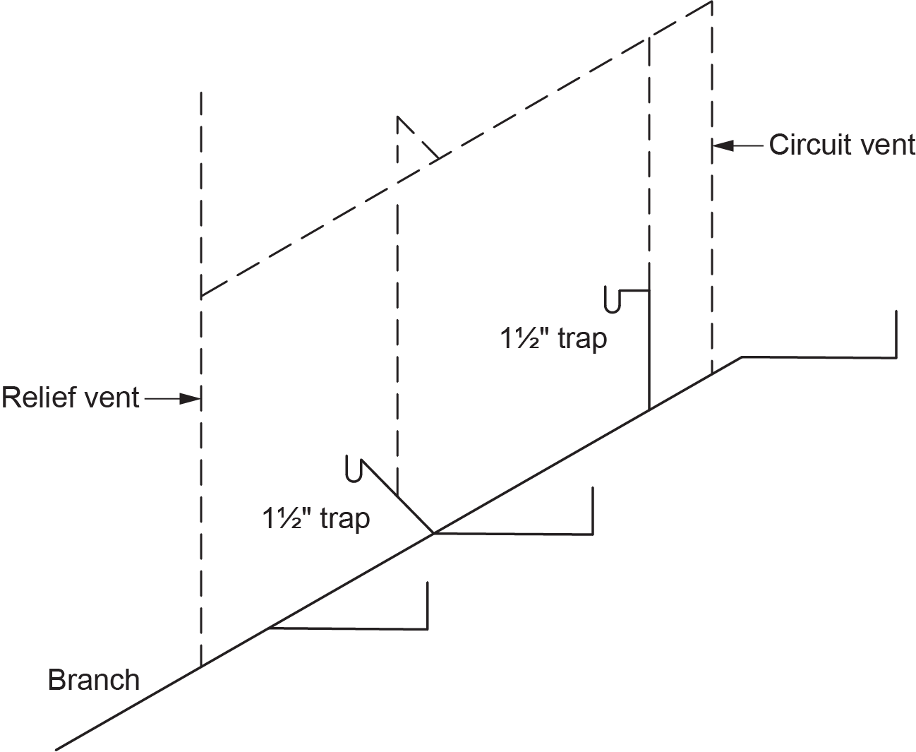
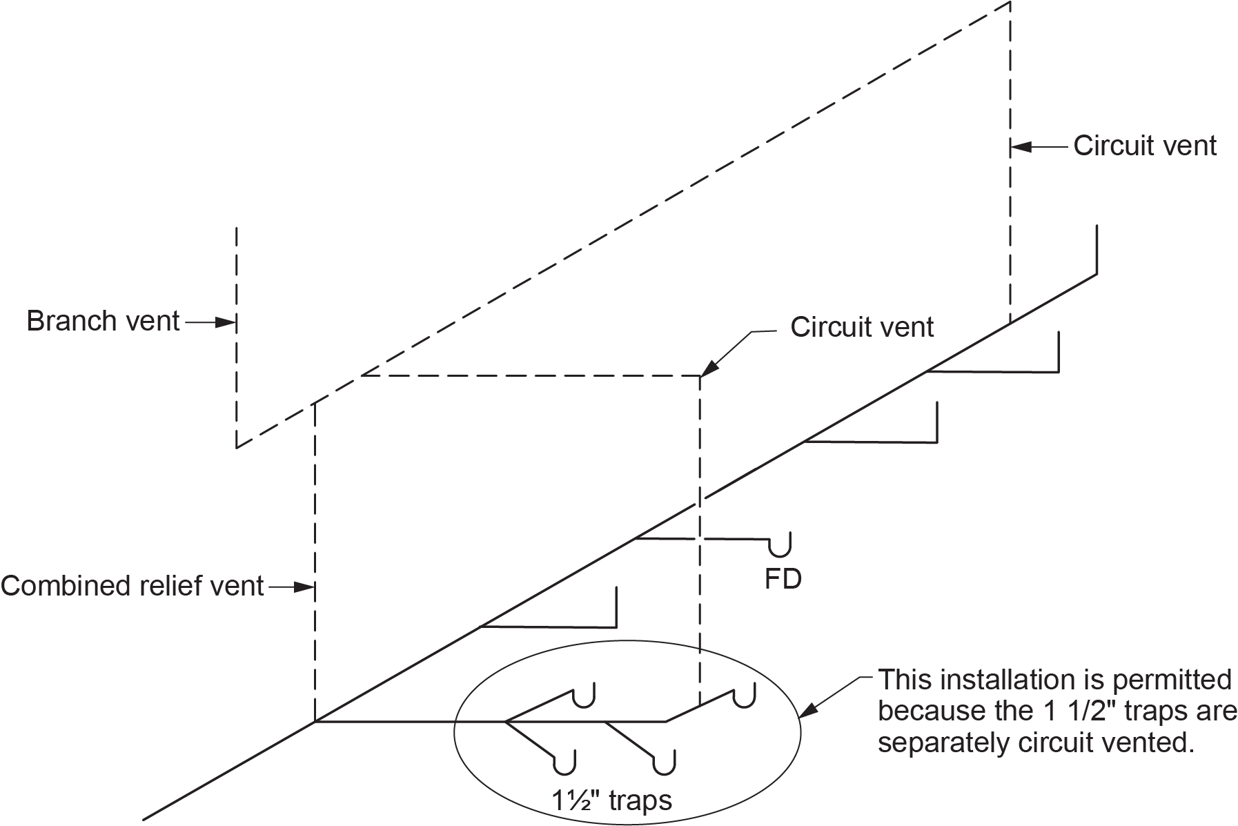
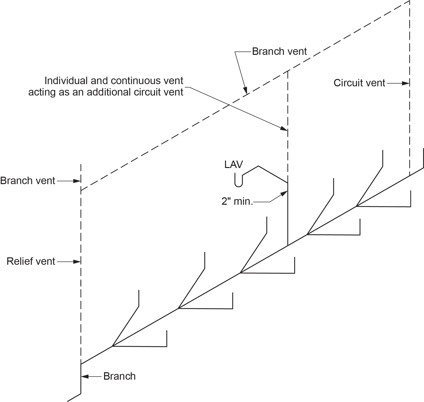
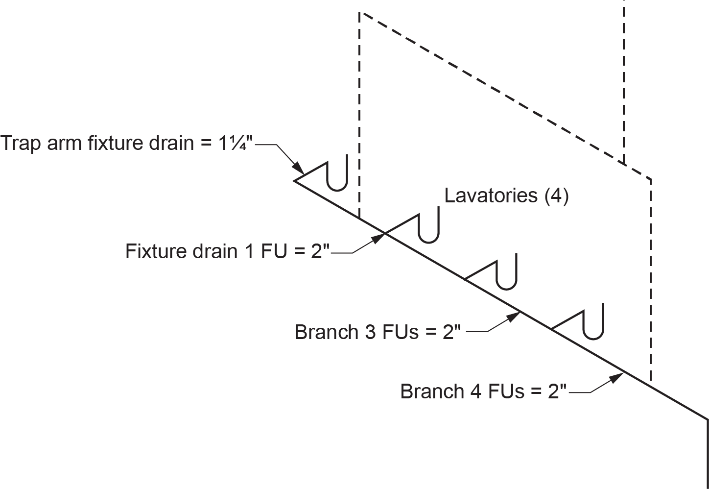
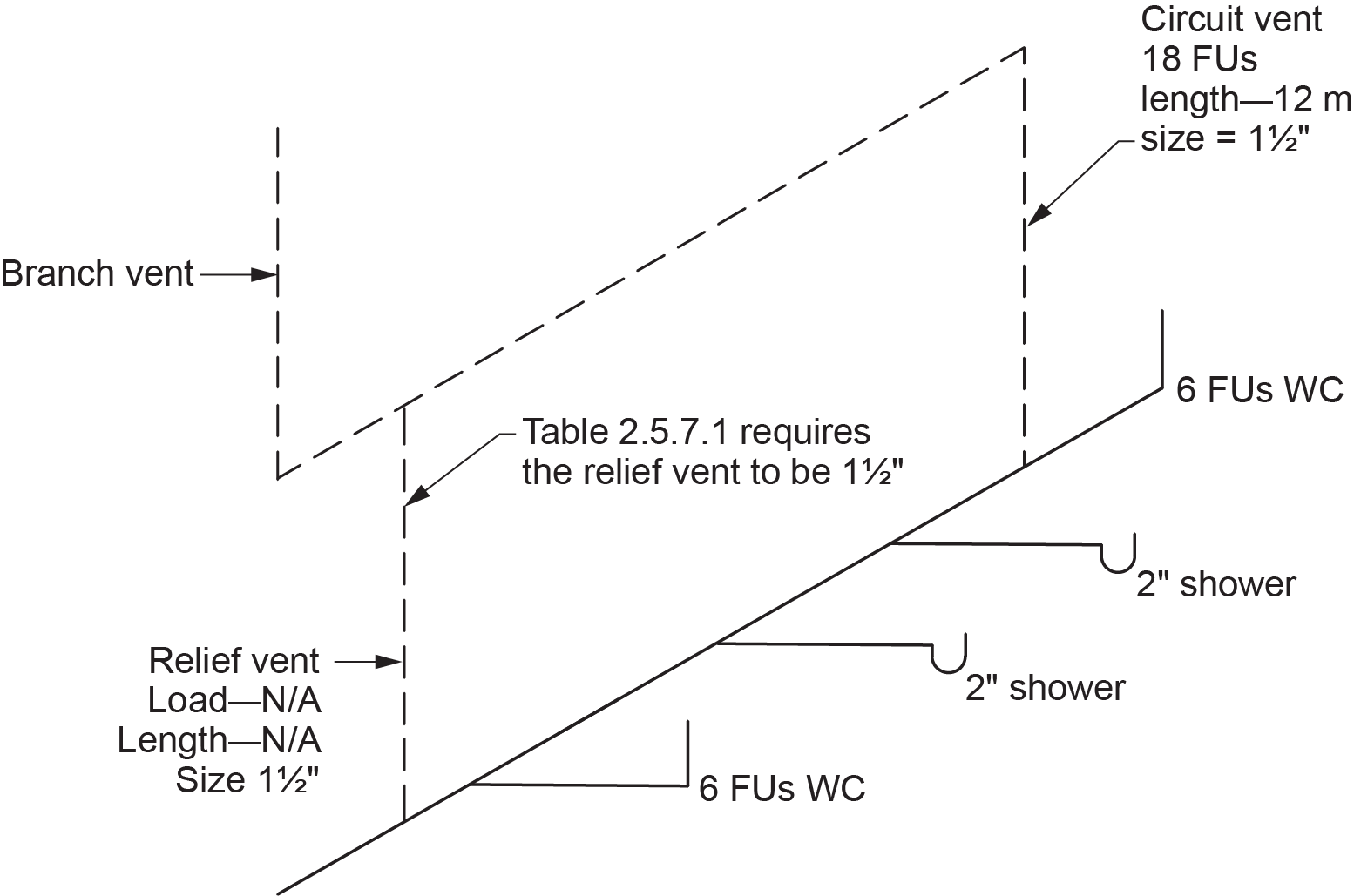
Fixtures with fixture outlet pipes less than 50 mm (2 in.) in size must be separately vented or separately circuit-vented (Figure 6) as per Clause 2.5.3.1.(2).
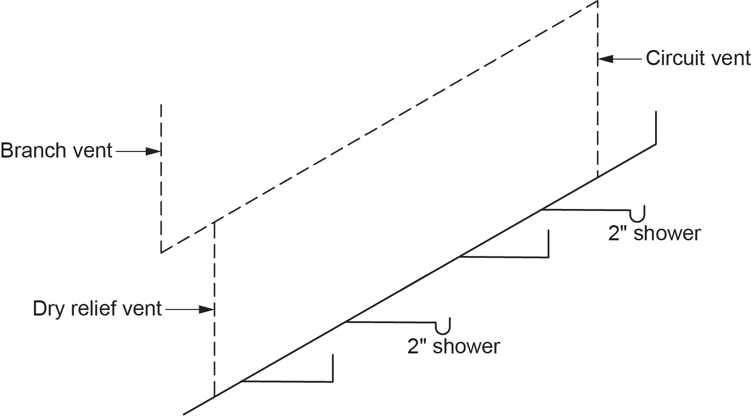
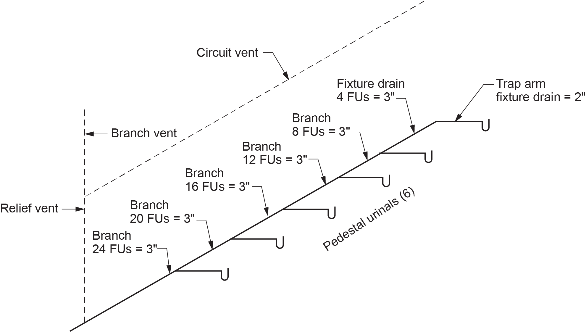
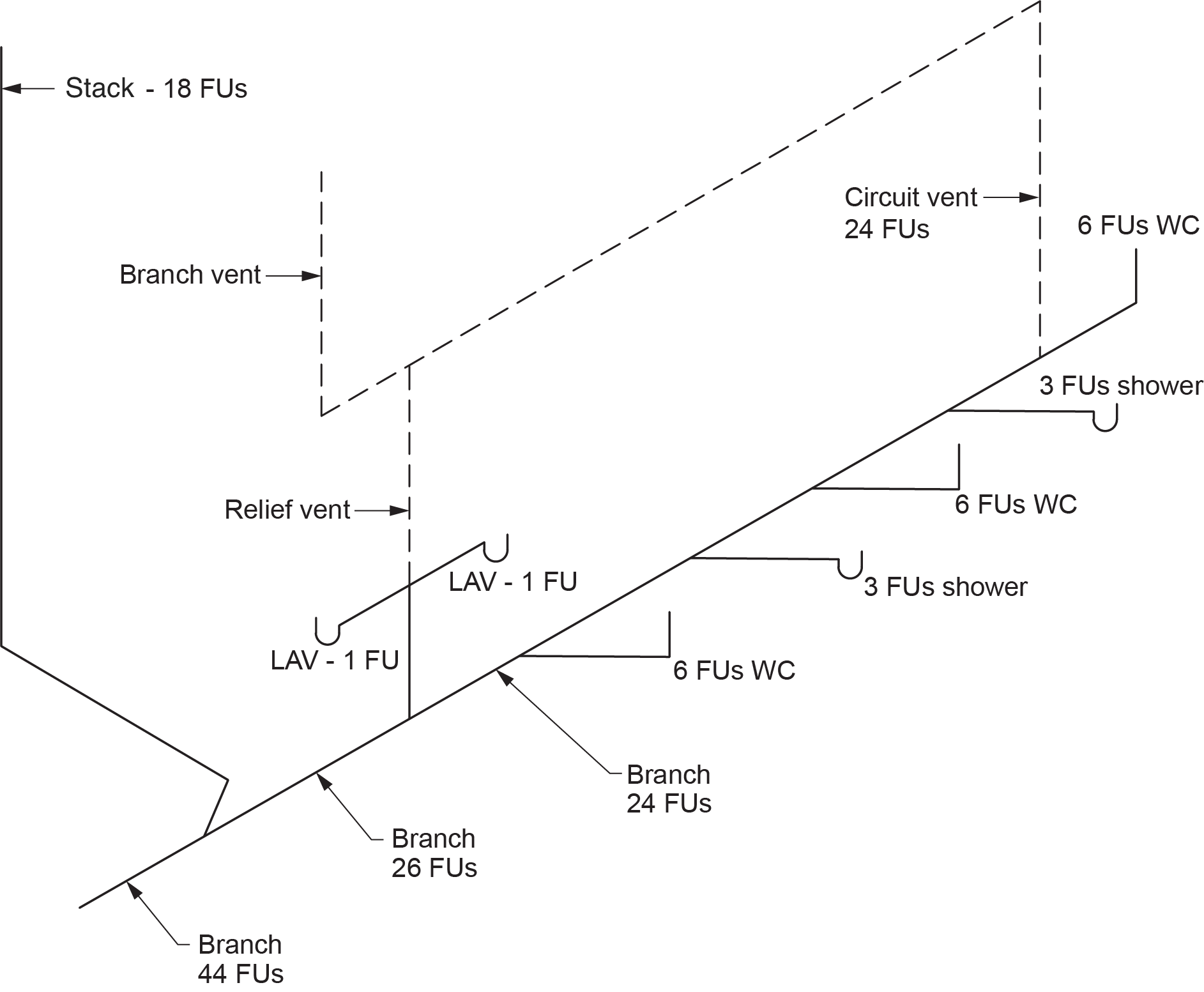
A relief vent must be connected to the branch that forms part of a circuit-vented system, downstream of the connection of the most downstream circuit-vented fixture. This relief vent may be a dry vent (Figures 7 and 8).
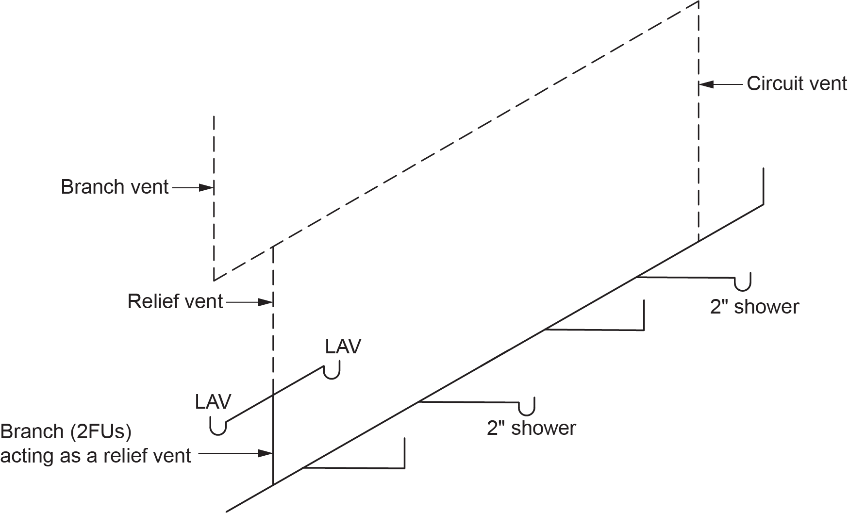
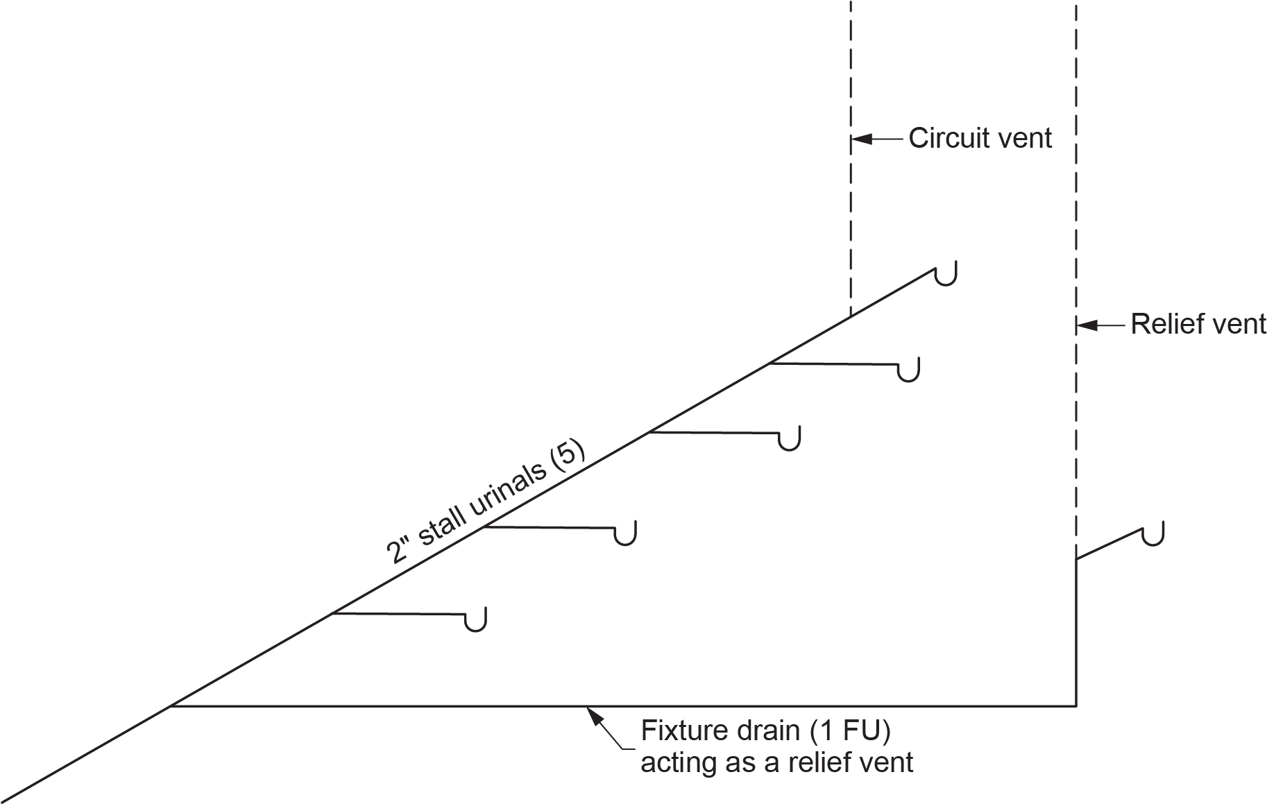
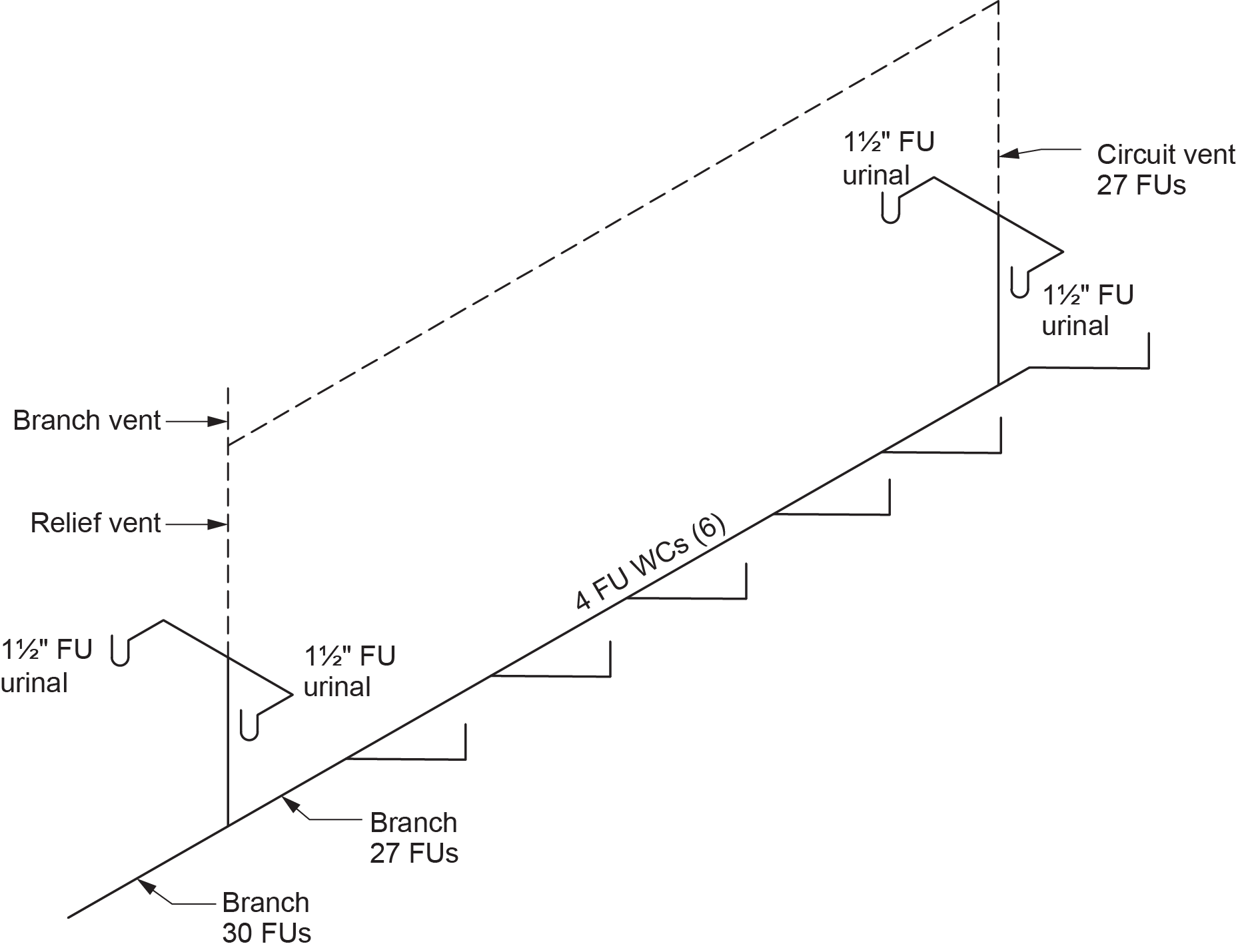
A sanitary drainage pipe cannot have a hydraulic load of more than 6 FUs when acting as a relief vent. If the sanitary drainage pipe is acting as a relief vent, it may be installed either horizontally or vertically (Figures 9 and 10).
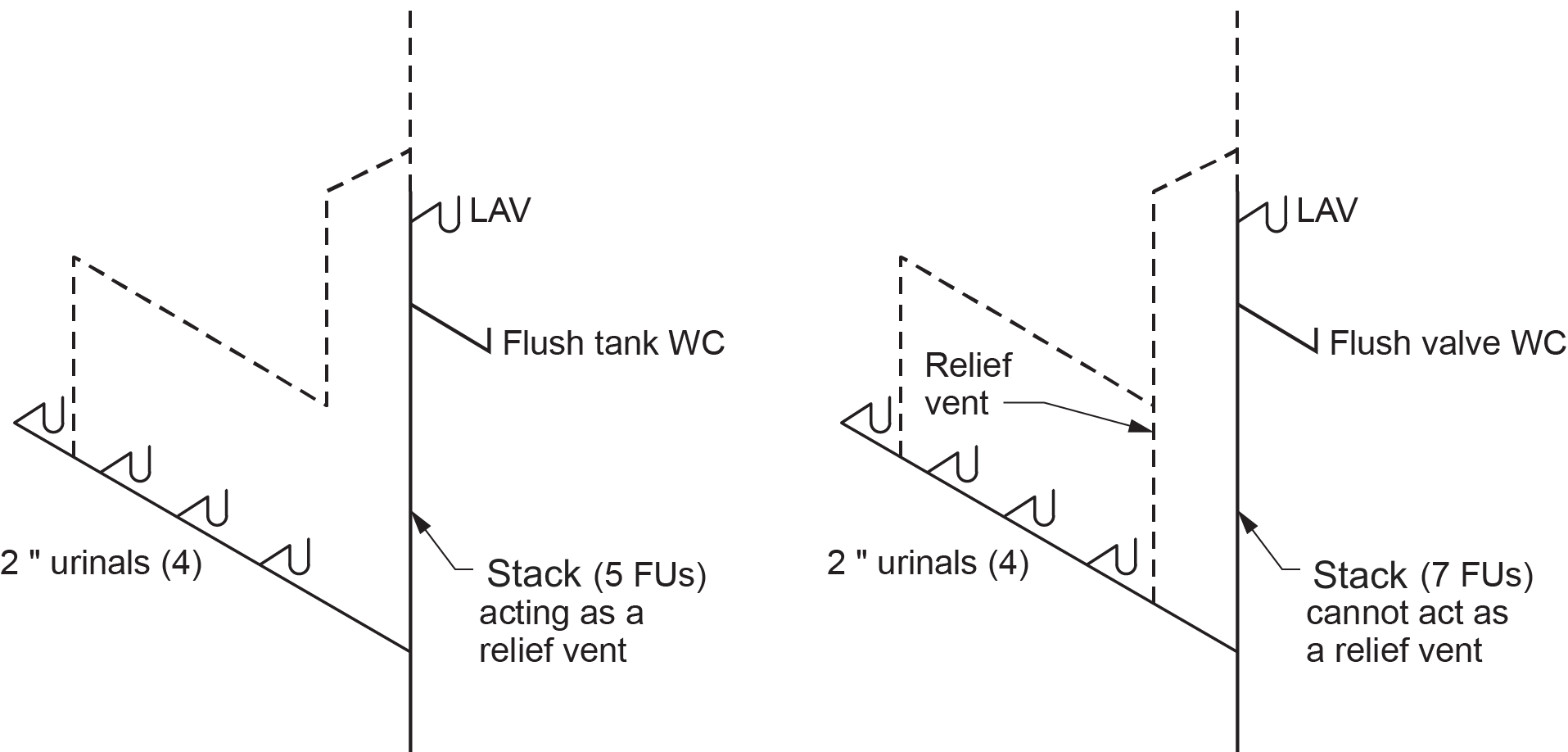
A stack may act as a relief vent for a circuit-vented branch. If there are more than 6 FUs on the sanitary drainage pipe (stack), a relief vent must be added.
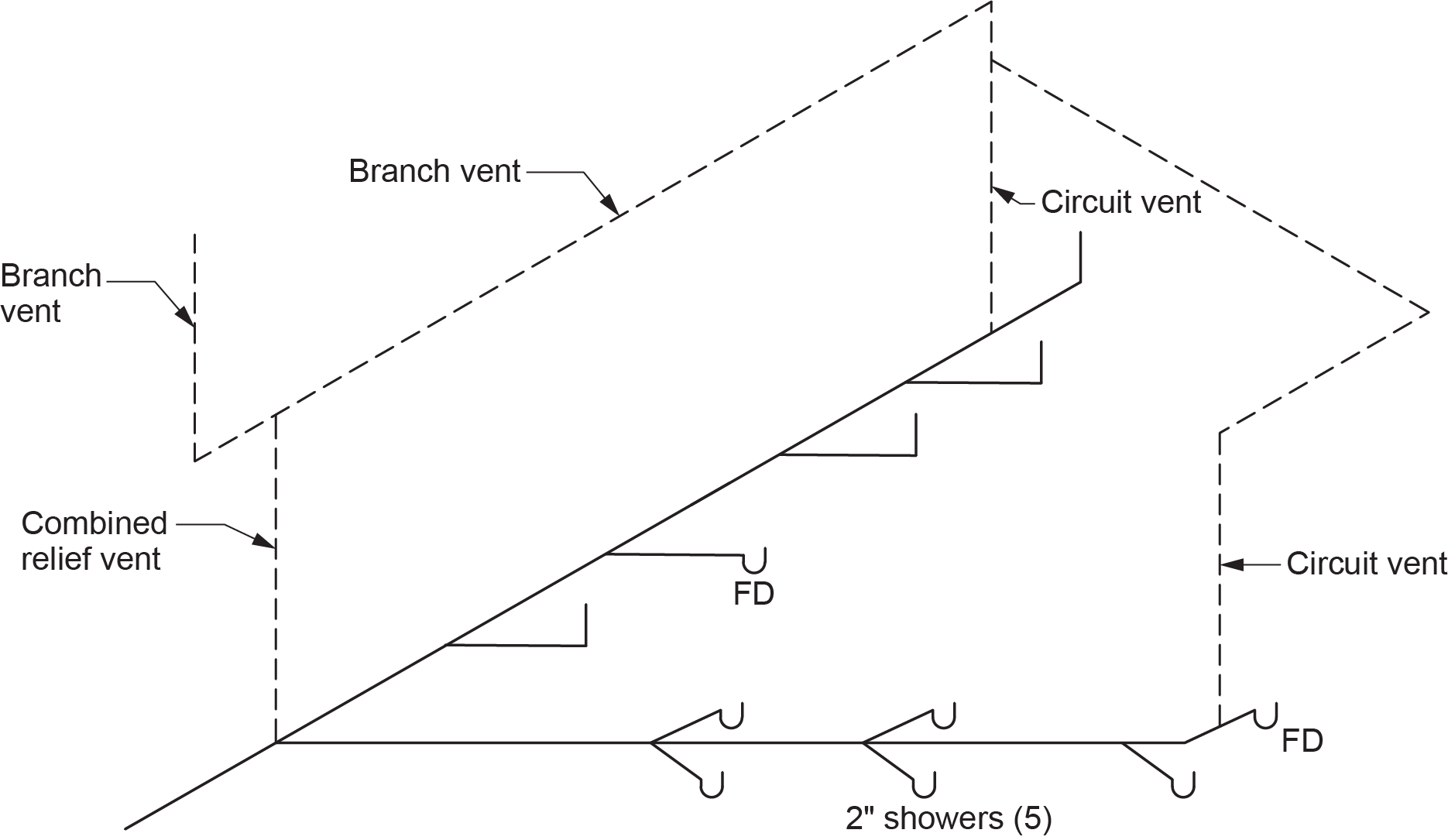
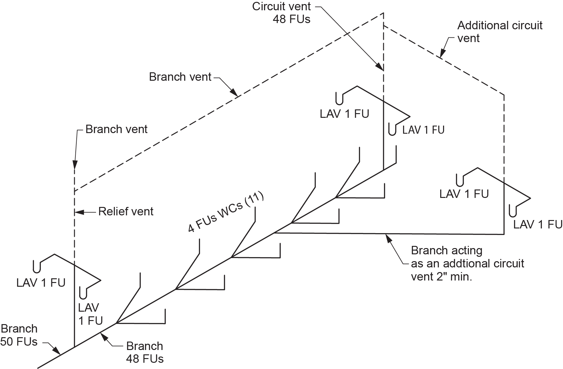
A symmetrically connected relief vent can serve as a combined relief vent for a maximum of two circuit-vented branches, provided there are not more than eight circuit-vented fixtures connected between the combined relief vent and each circuit vent (Figure 11).
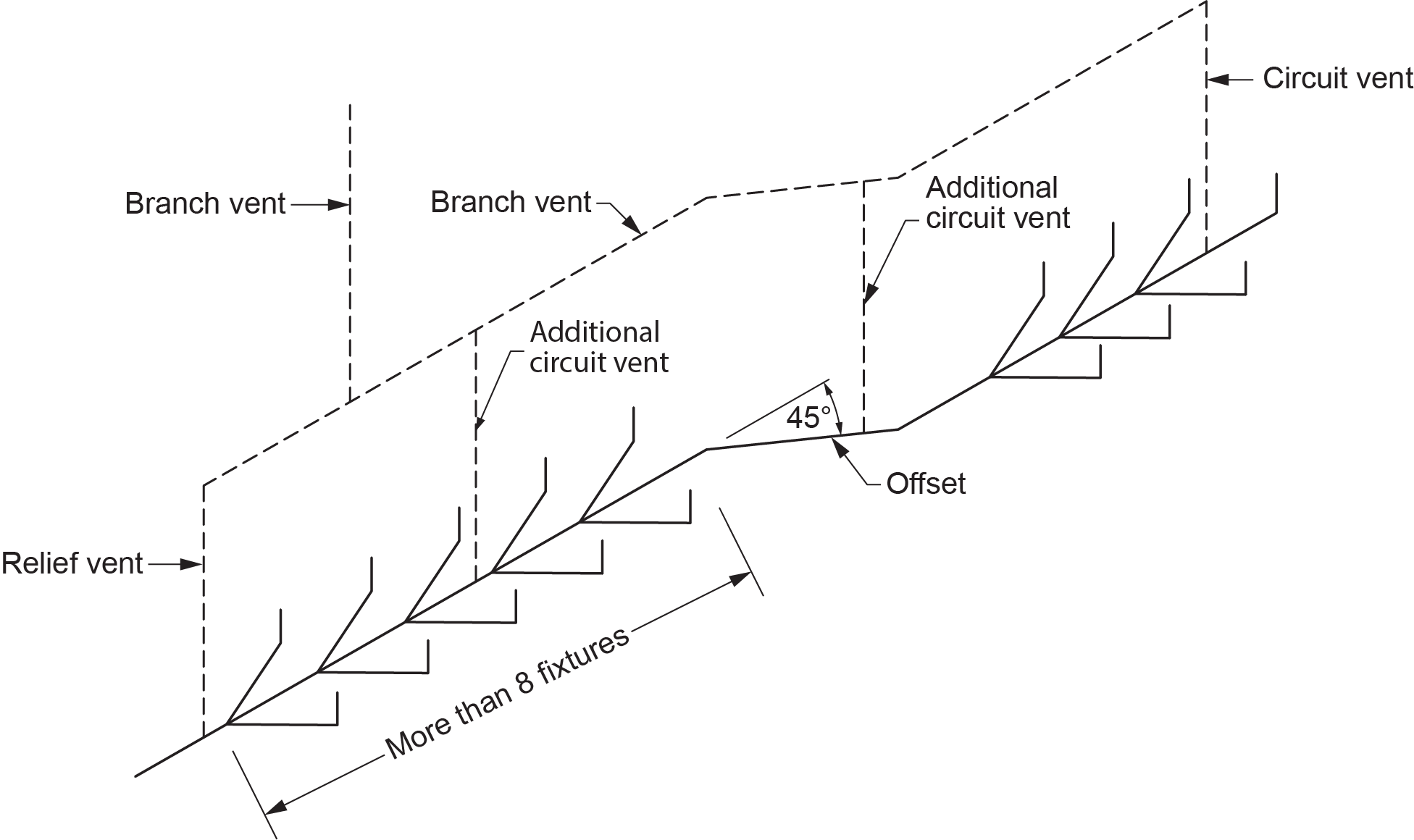
Additional circuit vents are required where:
- Each cumulative horizontal change in direction of a branch served by a circuit vent exceeds 45° between vent pipe connections.
- More than eight circuit-vented fixtures are connected to a branch between vent pipe connections.
Figure 12 shows additional circuit vents serving a circuit-vented branch, thus allowing more than eight fixtures and the cumulative change of direction between vent pipes.
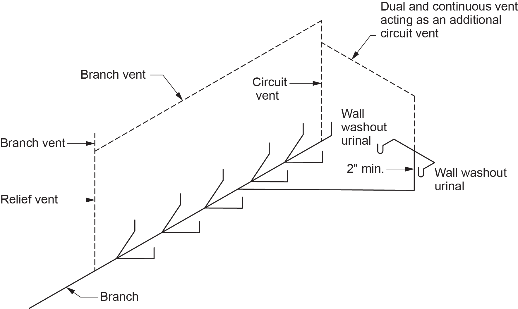
A sanitary drainage pipe can serve as an additional circuit vent provided:
- The sanitary drainage pipe is sized as a wet vent and is not less than 50 mm (2 in.) in size (Figure 13).
- The maximum number of fixtures does not exceed two.
- The fixture(s) connected to the vent has a maximum hydraulic load of 1.5 FUs each.
- When two fixtures connect to the vent pipe, the connection is made using a double sanitary tee fitting.
Figure 14 shows a sanitary drainage pipe acting as an additional circuit vent. The branch is sized as a wet vent with a minimum diameter of 2 in.
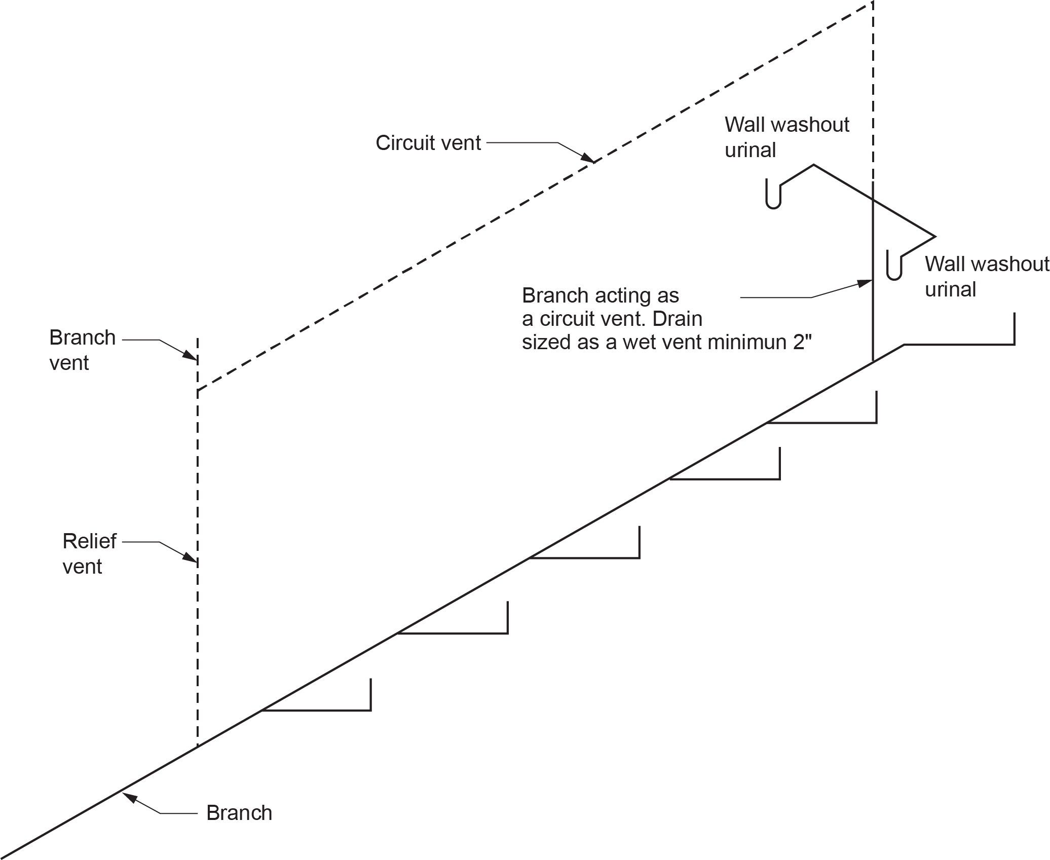
A trap arm(s) may be connected to a circuit vent (Figure 15), provided that:
- The branch or fixture drain is sized as a wet vent and is not less than 50 mm (2 in.) in size.
- The maximum number of fixtures does not exceed two.
- The fixture(s) connected to the circuit vent has a maximum hydraulic load of 1.5 FUs each.
- When two fixtures are connected to the vent pipe, the connection is made using a double sanitary tee fitting, as stated in Clause 2.5.4.5.(1).
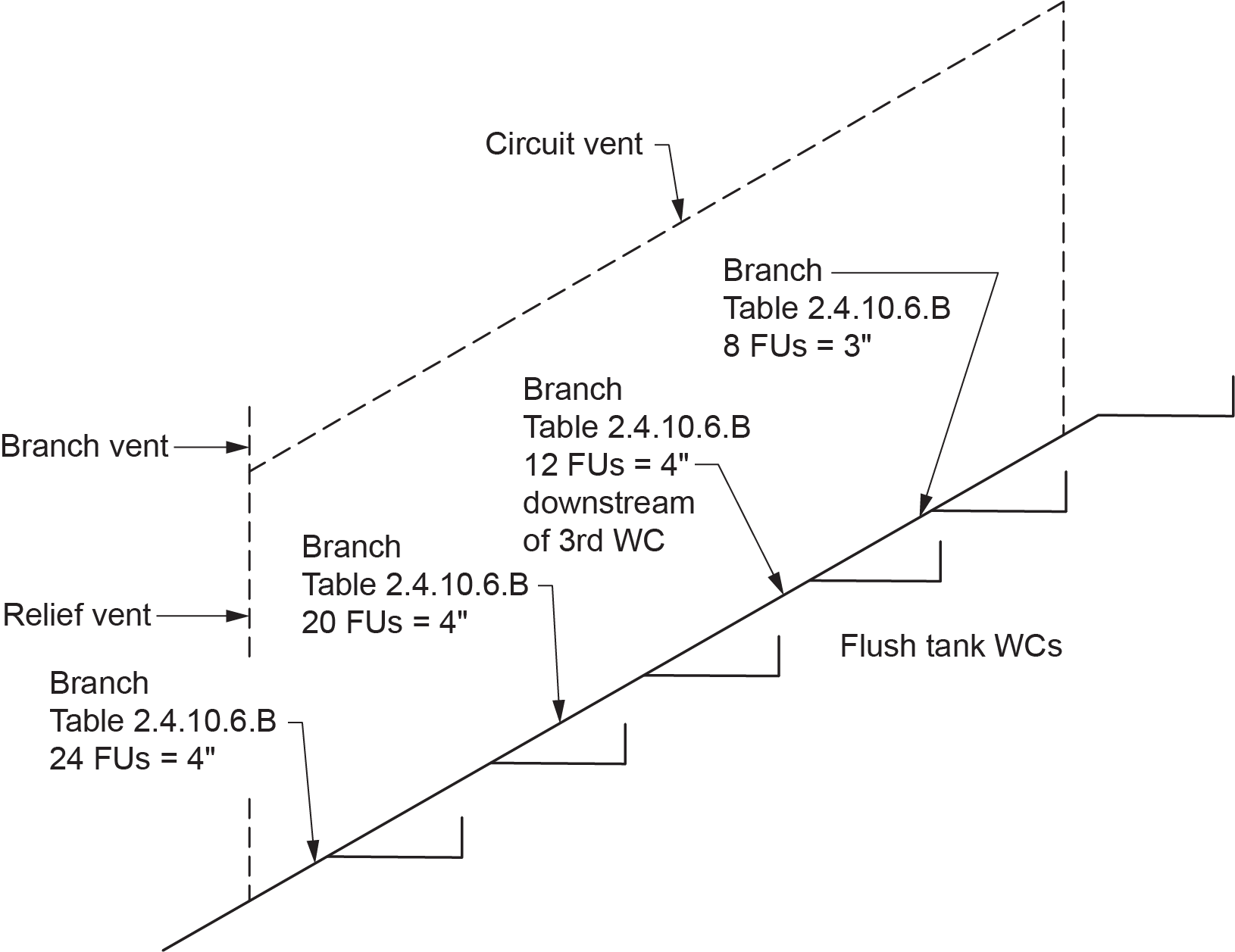
Circuit-vented branches, including the fixture drain downstream of the circuit vent connection, shall be sized as a branch from Table 2.4.10.6.-B (NPC, 2020, B 2-35; refer to Figures 16–18 below), except that it shall be not less than:
- 50 mm (2 in.), where traps less than 50 mm in size are circuit-vented.
- 75 mm (3 in.), where traps 50 mm in size or larger are circuit-vented.
The minimum size of an additional circuit vent or relief vent serving a circuit-vented branch need only be one size smaller than the size of the circuit vent, provided it conforms to the minimum vent requirements set out in Table 2.5.7.1., based on the size of the circuit-vented traps (Figures 19–21). If these requirements are met, the vents need not be larger than 50 mm (2 in.).
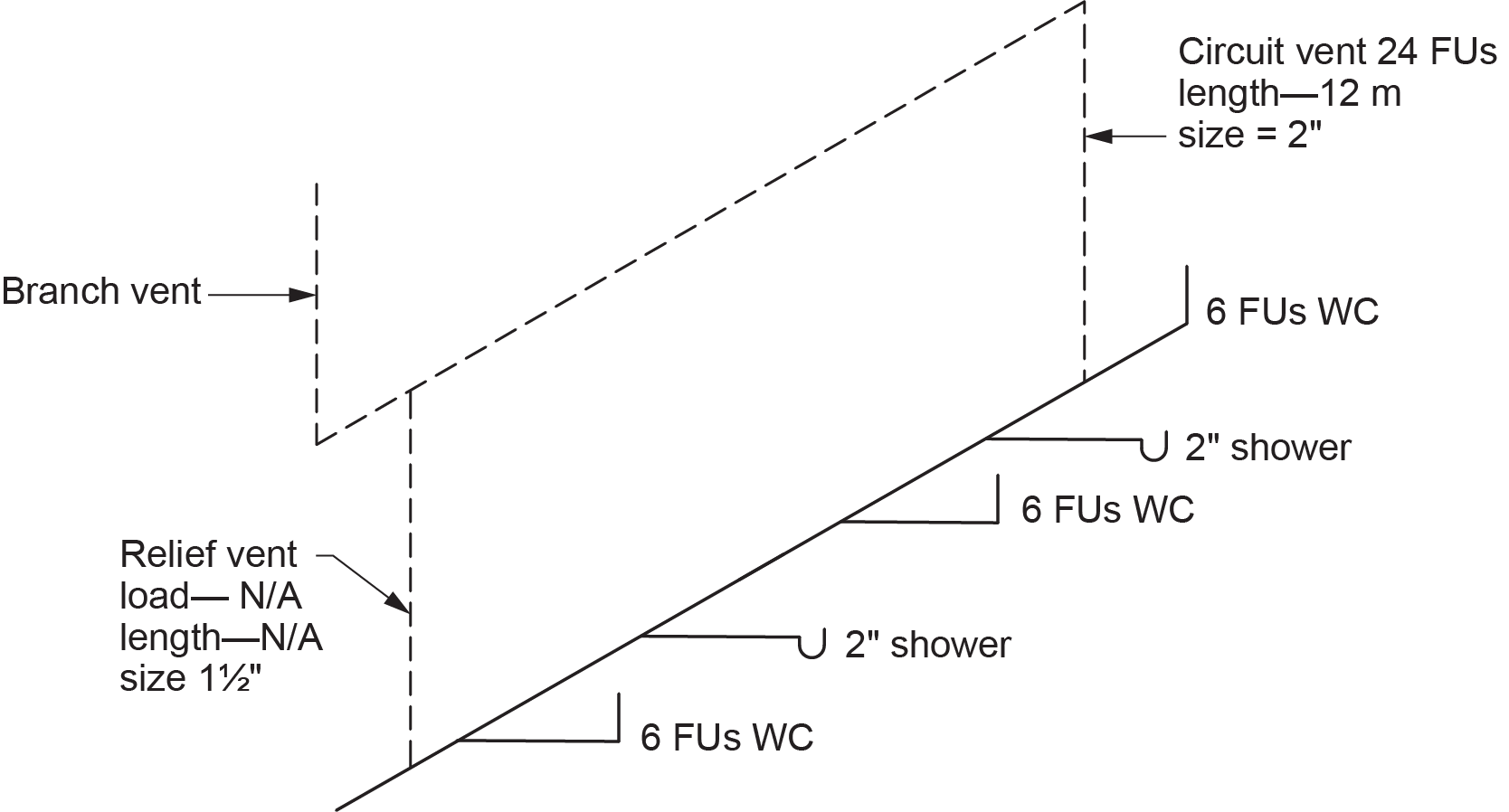
Figure 20 shows a relief vent and additional circuit vents serving a circuit-vented branch. The vents are sized one size smaller than the circuit vent and are in compliance with Table 2.5.7.1 (NPC, 2020, B 2-43).
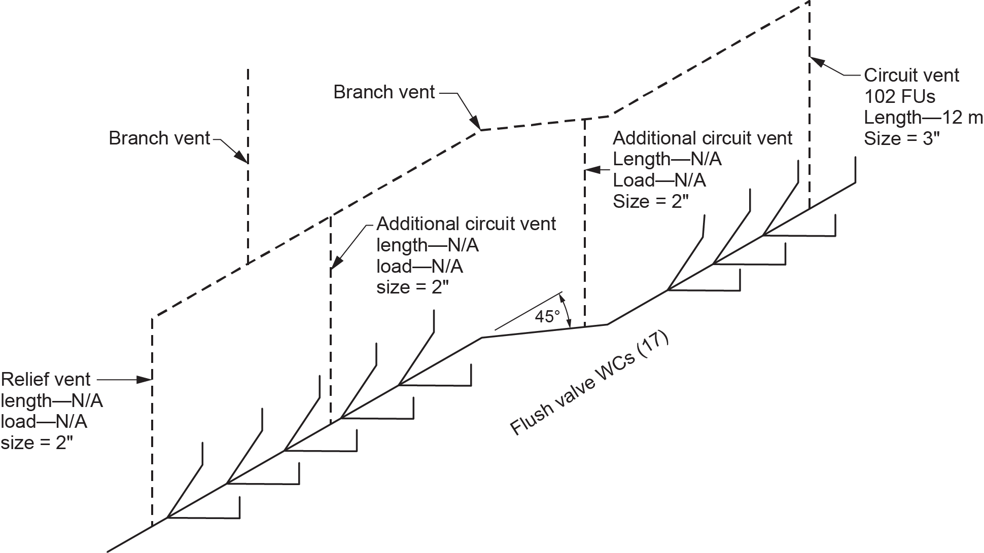
Figure 21 shows a relief vent serving a circuit-vented branch. The relief vent is sized equal to the circuit vent in order to comply with Table 2.5.7.1.
The hydraulic load on a circuit vent must include the hydraulic load from fixtures connected to the branch served by the circuit vent but must not include the hydraulic load connected to the sanitary drainage pipe acting as the relief vent (Figures 22–25).
 Self-Test D-1.8: Sizing Branch and Circuit Vents
Complete Self-Test D-1.8 and check your answers.
If you are using a printed copy, please find Self-Test D-1.8 and Answer Key at the end of this section. If you prefer, you can scan the QR code with your digital device to go directly to the interactive Self-Test.

References
National Research Council of Canada. (2020). National plumbing code of Canada 2020. Canadian Commission on Building and Fire Codes. https://nrc-publications.canada.ca/eng/view/ft/?id=6e7cabf5-d83e-4efd-9a1c-6515fc7cdc71
Skilled Trades BC. (2021). Book 2: Install fixtures and appliances, install sanitary and storm drainage systems. Plumber apprenticeship program level 2 book 2 (Harmonized). Crown Publications: King’s Printer for British Columbia.
Trades Training BC. (2021). D-1: Install sanitary drain, water and vent systems. In: Plumber Apprenticeship Program: Level 2. Industry Training Authority, BC.
Media Attributions
All figures are used with permission from Skilled Trades BC (2021) unless otherwise noted.
A type of vent that serves multiple fixtures on a horizontal drainage branch by utilizing the top portion of the pipe for ventilation. (Section D-1.8)
