D-1.6 Sizing Single-Storey Vents
The purpose of the venting system is to supply a free flow of air to maintain near-atmospheric-pressure conditions in the drainage system so fixtures can operate correctly.
Sizing a pipe for a venting system requires you to be familiar with both tables and clauses provided in the code book.
National Plumbing Code (NPC) Tables Used for Vents Serving Single Storey Fixtures
The NPC tables provide the minimum size of all vent pipes based on criteria, such as trap size, maximum fixture unit load it can carry, and the developed length of the vent.
The following are the tables you will need to refer to when sizing vents serving fixtures located on a single storey.
Table 2.5.7.1. — Minimum Permitted Size of Vent Pipe Based on Size of Trap Served
The NPC requires that the size of every vent pipe shall conform to Table 2.5.7.1. (NPC, 2020, B 2-43; refer to our Table 1), which takes precedence over all other venting tables. This is the only venting table that has an influence on the size of every vent pipe in the system, regardless of its name.
| Trap Size Served (in.) | Minimum Vent Pipe Size (in.) |
|---|---|
| 1.25 | 1.25 |
| 1.5 | 1.25 |
| 2 | 1.5 |
| 3 | 1.5 |
| 4 | 1.5 |
| 5 | 2 |
| 6 | 2 |
Table 2.5.8.1. — Maximum Permitted Hydraulic Loads Drained to a Wet Vent
A wet vent is simply a sanitary drainage pipe that serves as both a drain and a vent. Nearly every DWV system uses wet vents for material savings and space considerations. Because a wet vent must be able to drain the wastewater while providing air to protect the traps, it will be sized larger to accommodate the dual function.
Earlier in this section you were asked to identify certain DWV pipes by their function in the system. Whenever a sanitary drainage pipe serves both a drain and a vent pipe, it is said to be “acting as a wet vent.” During your exercise, some of the piping that matched this description were:
- Fixture drain acting as a wet vet
- Branch acting as a wet vet
- Stack acting as a wet vent
Whenever a pipe is “acting as a wet vent,” you must use Table 2.5.8.1. (NPC, 2020, B 2-44; refer to our Table 2) to check it for minimum size as a wet vent against any other factors such as being a fixture drain, branch or a stack.
This table states the total fixture units that may discharge into a wet vent above the most downstream wet-vented fixture or two symmetrically connected wet-vented fixtures. The fixture unit load from the lowest connecting fixture or fixtures in a wet-vented group, whether a water closet or not, are not counted when determining the load on the wet vent. In the table below, the second column is for sizing wet vents that do not serve water closets, and the third column is for wet vents that do serve water closets. Of special note is that the minimum size of a wet vent not serving water closets is [latex]1\tfrac{1}{2}[/latex] in. and, the minimum size of a wet vent serving a water closet is 2 in.
| Size of Wet Vent (in.) | Maximum Hydraulic Load (FUs) | |
|---|---|---|
| Not Serving Watering Closets | Fixtures Other Than Water Closets That Serve Not More Than Two Water Closets | |
| 1.5 | 2 | — |
| 2 | 4 | 3 |
| 3 | 12 | 8 |
| 4 | 36 | 14 |
| 5 | — | 18 |
| 6 | — | 23 |
Table 2.5.8.3. — Sizing of Branch Vents, Vent Headers, Circuit Vents and Continuous Vents
Table 2.5.8.3. (NPC, 2020, B 2-45; refer to our Table 3) provides the minimum size for four different vent types used in DWV systems and is based on the following information:
- Maximum fixture unit load it can carry
- The developed length of the vent
- This component is the major difference between sizing drainage pipe and vent pipe. The length of the vent is important because when air flows in a pipe there is a pressure loss due to the friction between the air and the pipe wall. The maximum length of vent piping for any particular size will limit the pressure drop within the venting system to 1 in. of water column, which is not substantial enough to cause a trap seal loss.
Example
To size a branch vent with a hydraulic load of 47 FUs and a developed length of 13 m (42 ft 7 in.), you would follow these steps:
- Find a hydraulic load in the left-hand column that is equal to or greater than the load in the example. In this case you have a load of 47 FUs, so the choice you would make is 60 FUs.
- Move to the right until you find a developed length that is greater than or equal to the length in the example of 13 m. The table entry of 15 m is the correct choice.
- Move vertically up the table to find the size of the vent = 2 in.
| Total Hydraulic Load Served by Vent Pipe (FUs) | Size of Vent Pipe (in.) | |||||||
|---|---|---|---|---|---|---|---|---|
| 1.25 | 1.5 | 2 | 3 | 4 | 5 | 6 | 8 | |
| Maximum Length of Vent Pipe (m) | ||||||||
| 2 | 9 | NL | NL | NL | NL | NL | NL | NL |
| 8 | 9 | 30 | 61 | NL | NL | NL | NL | NL |
| 20 | 7.5 | 15 | 46 | NL | NL | NL | NL | NL |
| 24 | 4.5 | 9 | 30 | NL | NL | NL | NL | NL |
| 42 | NP | 9 | 30 | NL | NL | NL | NL | NL |
| 60 | NP | 4.5 | 15 | 120 | NL | NL | NL | NL |
| 100 | NP | NP | 11 | 79 | 305 | NL | NL | NL |
| 200 | NP | NP | 9 | 76 | 275 | NL | NL | NL |
| 500 | NP | NP | 6 | 55 | 215 | NL | NL | NL |
| 1,100 | NP | NP | NP | 15 | 61 | 215 | NL | NL |
| 1,900 | NP | NP | NP | 6 | 21 | 61 | 215 | NL |
| 2,200 | NP | NP | NP | NP | 9 | 27 | 105 | 335 |
| 3,600 | NP | NP | NP | NP | 7.5 | 18 | 76 | 245 |
| 5,600 | NP | NP | NP | NP | NP | 7.5 | 18 | 76 |
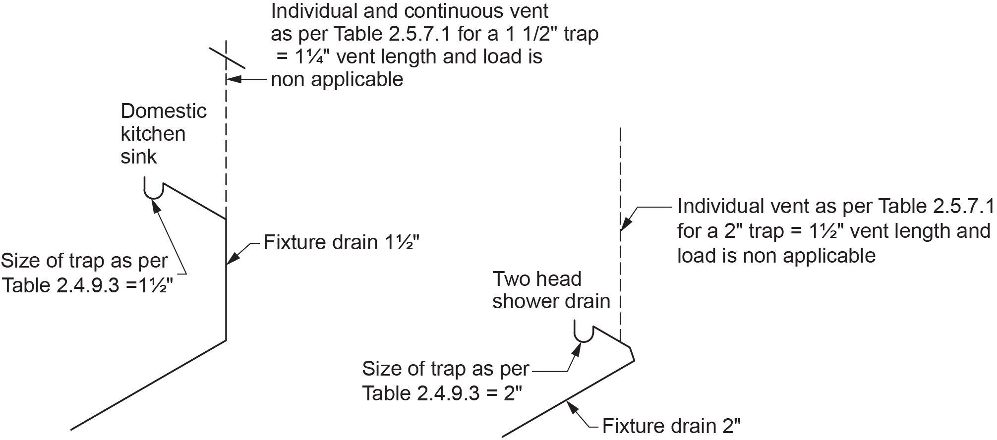
Sizing Individual Vents
An individual vent is installed in the nominally vertical position until it is above the flood level rim of the fixture that it is serving, protecting the individual fixture trap. The individual vent usually connects to the trap arm through a sanitary tee fitting.
There are two types of individual vents used in a venting system:
- Individual
- Individual and continuous
Both types of individual vents are sized by Code Clause 2.5.8.2., which directs you to refer to Table 2.5.7.1. The only consideration when sizing an individual vent is the size of trap served by the vent (Figure 1). To find the size of the trap, you would refer to Table 2.4.9.3. The size of the trap is the same as the fixture outlet pipe, which is given in the second column. The hydraulic load of the fixture and the length of the individual vent are considered non-applicable (N/A), as noted in Clause 2.5.8.2.(2).
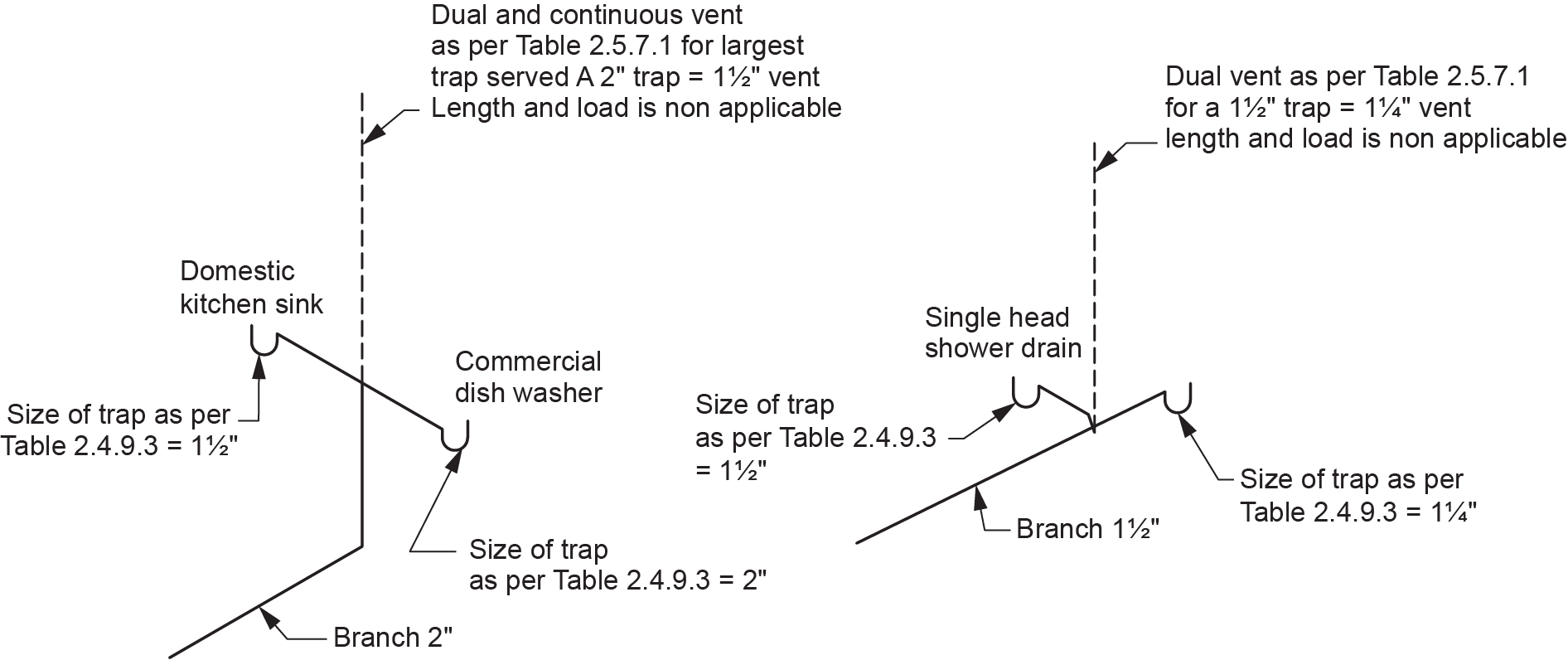
Sizing Dual Vents
Somewhat similar to individual vents, dual vents serve two fixtures, connected with a double fitting to a branch.
There are also two types of dual vents used in a venting system:
- dual
- dual and continuous
Like individual vents, dual vents are also sized by code Clause 2.5.8.2., which directs you to refer to Table 2.5.7.1 (NPC, 2020, B 2-43-44). The only difference is that the size of vent is dependent on the larger of the two traps served by the vent (Figure 2). To find the size of either trap, you would refer to Table 2.4.9.3. (NPC, 2020, B 2-31-32)., as before. The hydraulic load of the fixture and the length of the dual vent are considered non-applicable (N/A), as noted in Clause 2.5.8.2.(2).
Vents for Floor Drains
As stated in the drainage section, floor drains can be categorized as either non-emergency or emergency, and this designation determines whether or not the drain is given a hydraulic load. When it comes to venting floor drains, the NPC Clause 2.5.1.1.(3) states that if a trap serves as a floor drain, it need not be protected by a vent if the following conditions are present (NPC, 2020, B 2-37):
- The size of the trap is not less than 75 mm (3 in.).
- The length of the fixture drain is not less than 450 mm (17.7 in.).
- The fall on the fixture drain does not exceed its size.
In general terms, a floor drain could have a venting load, drainage load, both drainage and venting loads, or no load at all, depending on its size and designation. To make things easier to understand, Table 4 summarizes the different combinations created by the various rules governing floor drains.
| Floor Drain Designation | Drain Load (FUs) | Venting Load (FUs) |
|---|---|---|
| 2 in. non-emergency | 2 | 2 |
| 2 in. emergency | 0 | 2 |
| 3 in. non-emergency | 3 | 0 |
| 3 in. emergency | 0 | 0 |
The above summary table was laid out in the 1992 version of the BC Plumbing Code but has since escaped inclusion in subsequent editions of either the BCPC or NPC. Accordingly, most if not all jurisdictions still rely on this method of establishing loads on floor drains.
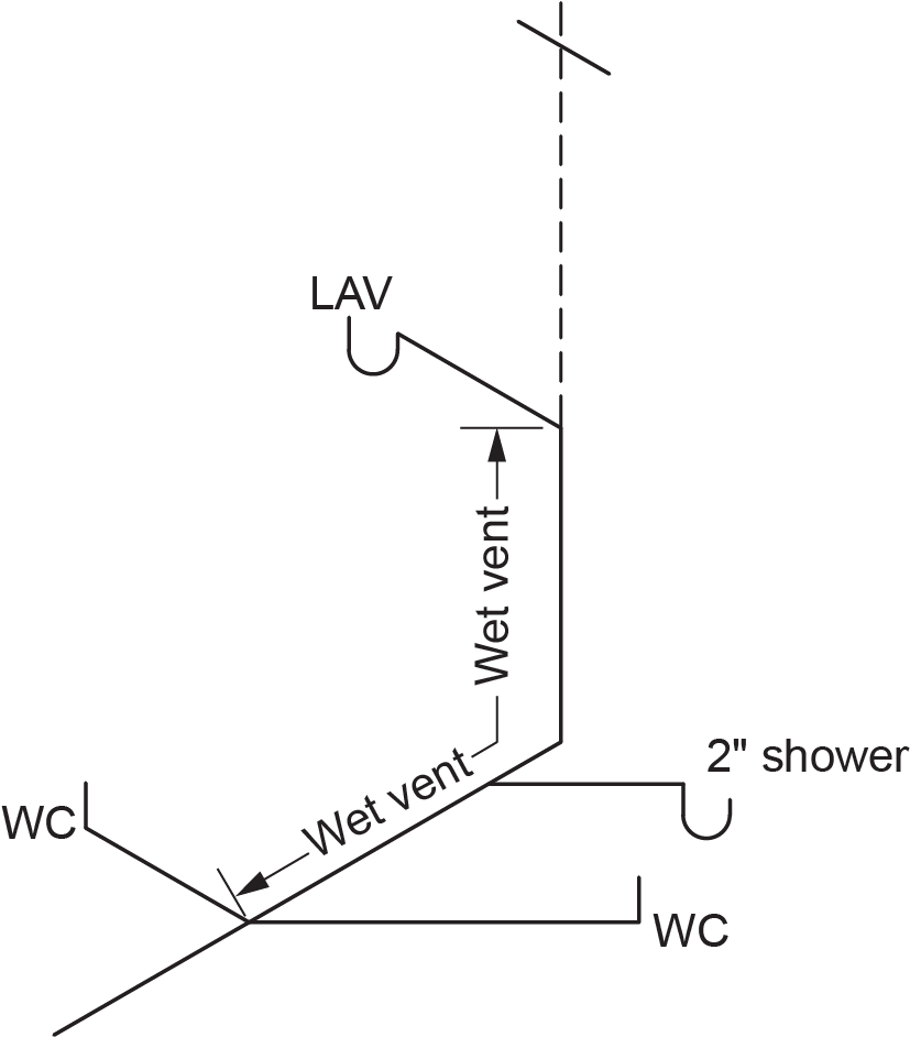
Sizing Wet Vents
Wet venting is a form of group venting based on the simple principle that wastewater clings to the side of a vertical waste pipe, leaving the centre core of the pipe open. This means a properly sized wet vent can have an open centre core of air to serve as a vent for fixtures downstream.
Plumbing code requirements for wet venting can be difficult to fully comprehend at first glance. With practice, the procedures presented here will become increasingly familiar. This skill will be advantageous to those performing plumbing layout work in the industry
Because wet vents can serve a group of fixtures on one or many levels, two categories of wet vents have been established by industry:
- Single-storey wet vents (fixture drain/wet vents and branch/wet vents)
- Multi-storey wet vents (stack wet vents)
The terms “single-storey wet vents” and “multi-storey wet vents” are not referenced in the code book as such. These terms are sometimes used as a learning tool or descriptor by educators to help learners visualize the concepts being explained. This textbook explores each category separately, keeping in mind that most of the following code requirements pertain to both types.
Sizing Single-Storey Wet Vents
The first step in sizing a wet vent is to become familiar with the code requirements stated in Section 2.5.2 of the NPC. (The remainder of this topic is quoted from this section of the NPC. Figures 3–9 illustrate bulleted points from this section.)
- The hydraulic load that drains to a wet vent shall conform to Table 2.5.8.1. This is the only table used to size the wet-vented portion of a drainage system.
- One or two water closets may connect to the wet vent, but they must be located furthest downstream, and if there are two water closets, they must be connected through a symmetrical fitting. This would be a double wye (if on a horizontal wet vent) or a sanitary cross (if on a vertical wet vent).
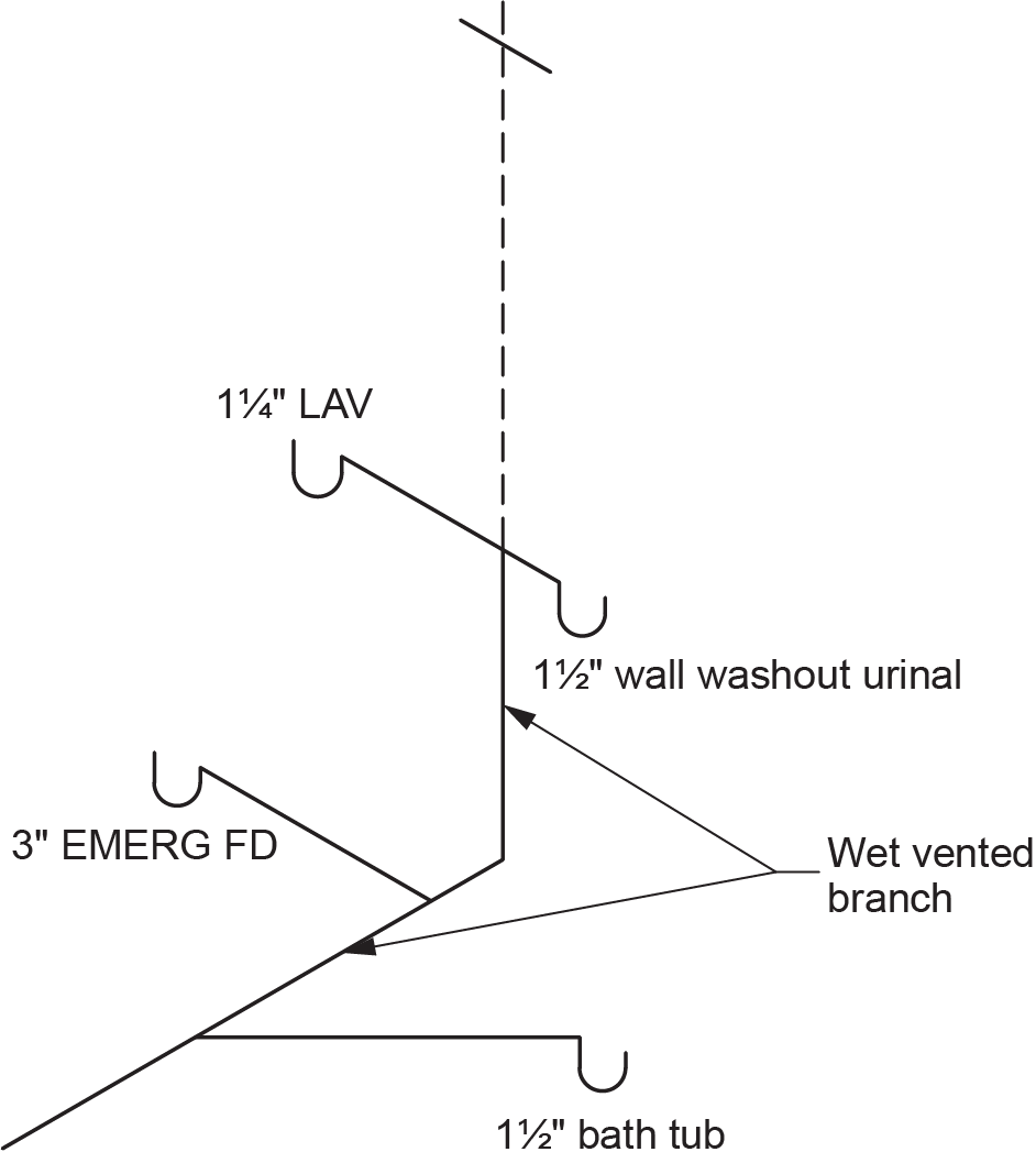
- Trap arms and fixture drains connected to the wet vent do not exceed 50 mm (2 in.) in size, except for connections from emergency floor drains (Figure 4).
- When determining the size of a wet vent, the hydraulic load to consider is the sum of all fixtures connected to the wet vent except for the most downstream fixture or symmetrically connected fixtures (Figure 5). Their load is not included when using Table 2.5.8.1. because the pipe below the lowest connection to the wet vent is only a drain and does not have to vent any fixtures through it. However, the lowest fixtures on the wet vent have to be included in the load of the drainage pipe, such as a branch, downstream of the wet vent.
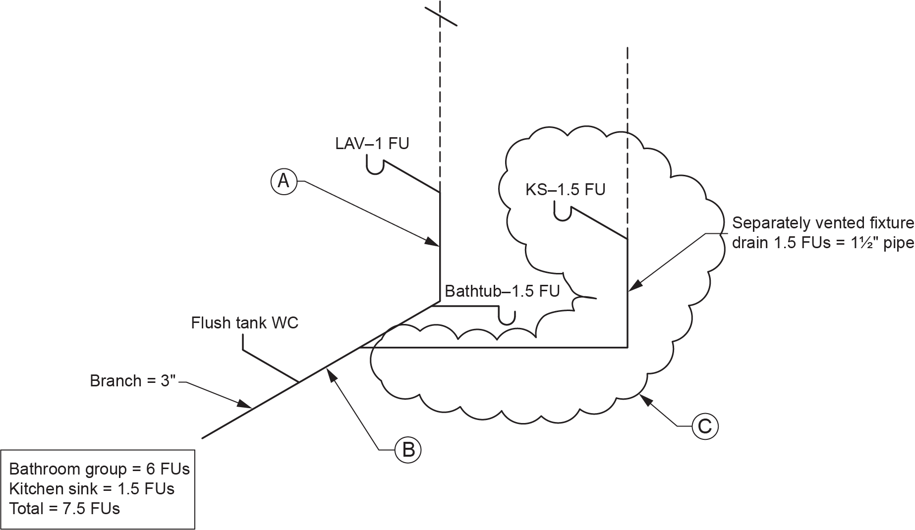
- Other separately vented fixtures — located in the same storey and having a total hydraulic load not greater than 2 FUs — are allowed to tie into a wet vent or a wet-vented water closet trap arm (Figures 6 and 7). When this is done, their fixture unit load will be added to the wet vent load.
- Figure 6:
- Fixture drain acting as a wet vent. 4 FUs serving water closets from Table 2.5.8.1. = 3 in. pipe (NPC, 2020, B 2-44). Furthest downstream fixture (WC) not included.
- Branch acting as a wet vent. 4 FUs serving water closets from Table 2.5.8.1. = 3 in. pipe. Furthest downstream fixture (WC) not included.
- Separately vented fixture connected to wet vent. The load of the kitchen sink must be added to the wet vent load.
- Figure 6:
-
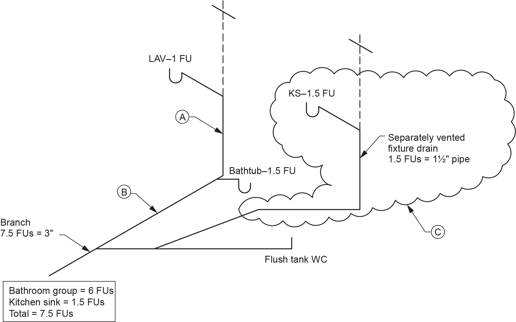
- Figure 7:
- Fixture drain acting as a wet vent. 4 FUs serving water closets from Table 2.5.8.1. = 3 in. pipe. Furthest downstream fixture (WC) not included.
- Branch acting as a wet vent. 4 FUs serving water closets from Table 2.5.8.1. = 3 in. pipe. Furthest downstream fixture (WC) not included.
- Separately vented fixture connected to wet vent. The load of the kitchen sink must be added to the wet vent load.
- Figure 7:
- The size of a wet vent will not reduce except for the portion upstream of the emergency floor drain (Figure 8).

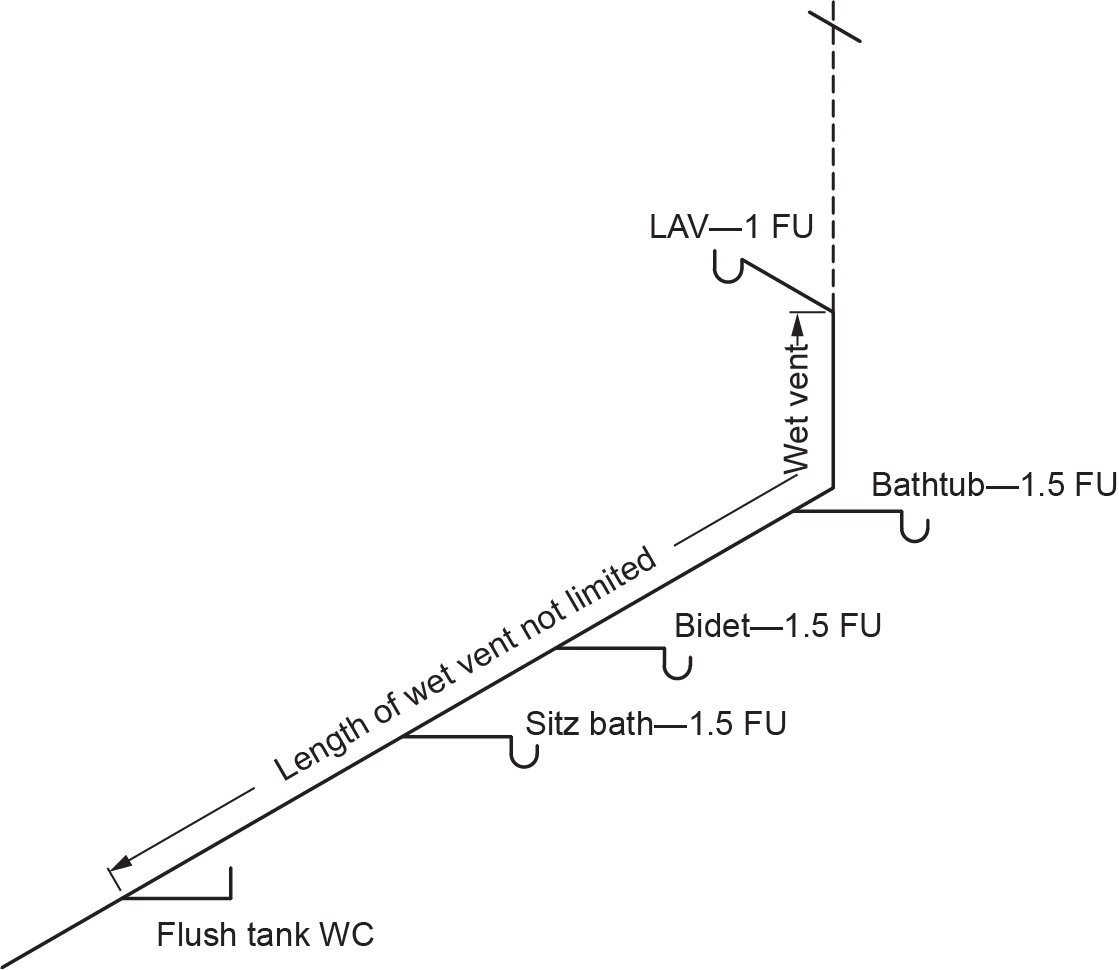
- The length of a wet vent is not limited. Wet vents are sized by fixture unit load not by length (Figure 9).
Sizing Continuous Vents Serving Single-Storey Wet Vents
The most common applications of continuous vents are when serving single-storey wet-vented fixture drains and branches. The continuous vent connects to the vertical pipe where the most upstream wet-vented fixture is connected. Sizing of the continuous vent is found on Table 2.5.8.3. in the NPC.
Note: As with any vent, the continuous vent can never be smaller than permitted by Table 2.5.7.1. For example, if the continuous vent serves a water closet, Table 2.5.8.3 may permit a [latex]1\tfrac{1}{4}[/latex] in. vent. Table 2.5.7.1. overrides this value, as a [latex]1\tfrac{1}{4}[/latex] in. vent can only serve [latex]1\tfrac{1}{4}[/latex] in. and [latex]1\tfrac{1}{2}[/latex] in. traps.
You need the following information when using Table 2.5.8.3.:
- The hydraulic load served by the continuous vent:
- The hydraulic load to consider is the total number of wet-vented fixtures, including the most downstream connected fixture(s). The hydraulic load is most often identical to the drainage branch downstream of the wet vent portion. The one exception to this situation is explained below:
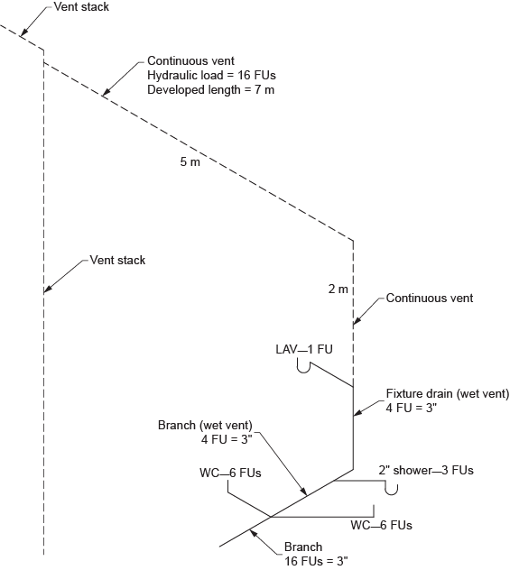
- The hydraulic load of separately vented fixtures draining into the wet vent is not included when sizing the continuous vent serving the wet vent (Figure 10).
- The hydraulic load to consider is the total number of wet-vented fixtures, including the most downstream connected fixture(s). The hydraulic load is most often identical to the drainage branch downstream of the wet vent portion. The one exception to this situation is explained below:
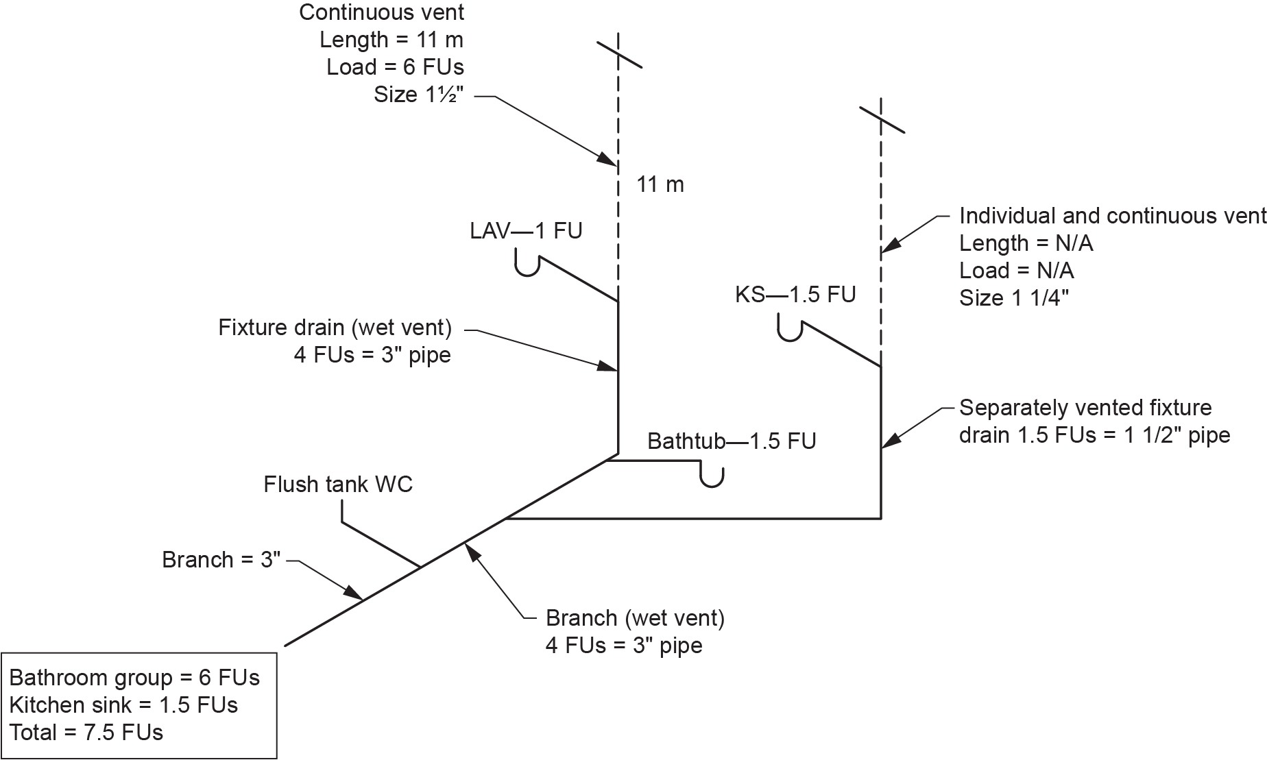
- The developed length of the vent measured from the vertical sanitary drainage pipe connection to where it joins a vent stack, stack vent, header (Category 3 or 4 vent) or measured through to open air (Figures 11 and 12).
The length and hydraulic load must be considered when sizing a continuous vent serving a single-storey wet-vented branch.
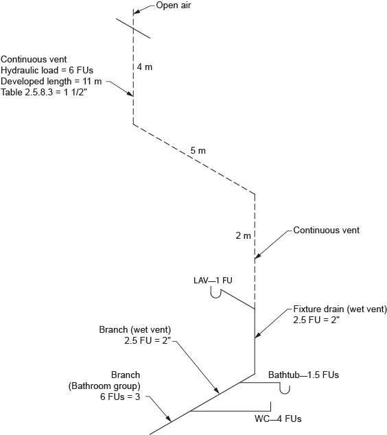
For the example in Figure 12, Table 2.5.8.3. states the continuous vent size is [latex]1\tfrac{1}{4}[/latex] in. However, Table 2.5.7.1. states the minimum size of all vent pipes for 2 in. and 3 in. traps must be at least [latex]1\tfrac{1}{2}[/latex] in.
 Self-Test D-1.6: Sizing Single-Storey Vents
Complete Self-Test D-1.6 and check your answers.
If you are using a printed copy, please find Self-Test D-1.6 and Answer Key at the end of this section. If you prefer, you can scan the QR code with your digital device to go directly to the interactive Self-Test.

References
National Research Council of Canada. (2020). National plumbing code of Canada 2020. Canadian Commission on Building and Fire Codes. https://nrc-publications.canada.ca/eng/view/ft/?id=6e7cabf5-d83e-4efd-9a1c-6515fc7cdc71
Skilled Trades BC. (2021). Book 2: Install fixtures and appliances, install sanitary and storm drainage systems. Plumber apprenticeship program level 2 book 2 (Harmonized). Crown Publications: King’s Printer for British Columbia.
Trades Training BC. (2021). D-1: Install sanitary drain, water and vent systems. In: Plumber Apprenticeship Program: Level 2. Industry Training Authority, BC.
Media Attributions
All figures are used with permission from Skilled Trades BC (2021) unless otherwise noted.
A plumbing fitting used to connect a vent pipe to a drain pipe while ensuring proper air circulation. (Section D-1.6)
