D-1.3 Functions of Different Pipes in a DWV System
Each DWV pipe has a specific name and function. Plumbers must thoroughly understand these terms to ensure the design and installation comply with code. Building drainage and venting systems must be appropriately sized based on the fixture unit load imposed on them by the fixtures and conform with other code clauses. Plumbers must also understand the mechanics of fluid flow in pipes to understand certain code regulations and their intent.
The DWV system is perhaps the most important part of the total mechanical system in a building. The sanitary drainage system is a circuit of piping designed to remove waterborne waste from the plumbing fixtures in a building and drain them safely, reliably, and efficiently. A sanitary drainage system typically consists of fixture drains, branches, and stacks conveying liquid waste to a building drain that, in turn, becomes a building sewer outside the building. The wastewater is then delivered to either a municipal sewer system at the street or to an on-site private sewage disposal system. A recent development in the handling of building waste is to have the drainage from sinks, showers, and dishwashers (known as grey water) drain to a tank, where it is treated and reused for toilet flushing and irrigation purposes.
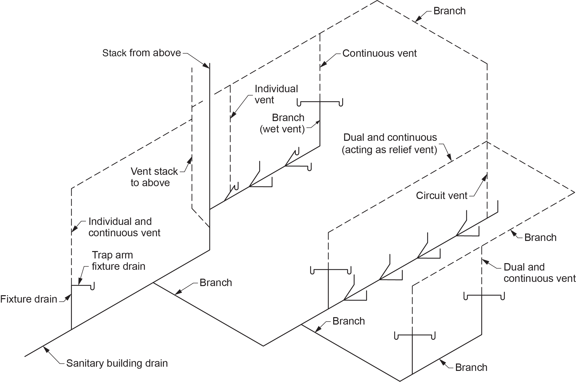
Along with all the drain and waste pipes, there is a system of vent pipes integrated into the DWV system that is critical for plumbing fixtures to function correctly (Figure 1). These vent pipes provide a free flow of air to maintain equalized pressure throughout the DWV systems and allow sewer gas to be vented out above the building, where it can quickly mix with the ambient air and dissipate. The vent piping allows the admission or emission of air into the system, limiting the pressure differential on the trap seals to not more than 1 in. water column (WC) (250 Pa).
This pressure limitation prevents back pressure or siphonage from removing the water trap seals that serve the fixture.
Parts of a DWV System
The main components to a DWV system include:
- Fixture outlet pipe
- P-trap
- Trap arm
- Fixture drain
- Branch
- Stack
- Sanitary building drain
- Sanitary building sewer
- Cleanouts
- Vents
Fixture Outlet Pipe
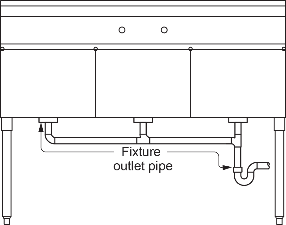
The fixture outlet pipe is the section of drain pipe between the drain outlet of a fixture and the trap serving it. Fixture outlet pipes are typically sized by the tailpiece outlet of the fixture, with some exceptions, such as a three-compartment commercial kitchen sink served by a single trap (Figure 2). The portion of the fixture outlet pipe serving all three sinks is increased by one size. Some fixture outlet pipes may also be reduced from the size of the outlet of the fixture. For example, a shower base is usually supplied with a 50 mm (2 in.) outlet but only requires a 38 mm ([latex]1\tfrac{1}{2}[/latex] in.) fixture outlet pipe if there is only one showerhead installed.
The maximum length of a fixture outlet pipe is limited to 1,200 mm (4 ft) to prevent the velocity of the water draining through it from siphoning the trap; this is known as “self-siphonage.” However, this length does create the ability to place a trap for a fixture under the floor and is useful for some installations.
P-Trap
A trap is a non-mechanical device that prevents odours, animals, and drafts from entering the building through it while not affecting the flow from the fixture when it drains. It is important to recognize the other two functions of a trap seal. The velocity of water moving through a trap is important to its function. This is why there are limits to how far below the fixture the trap can be placed. If the liquid has too much velocity when it reaches the trap, it could self-siphon, which would remove the trap seal. The pipe (trap arm) exiting the trap has to be nominally horizontal so that the water does not rush through and siphon the trap. Most traps are installed external to the fixture, but a few fixtures — such as toilets and some urinals — have built-in traps known as “integral traps.”
Trap Arm
A trap arm is the pipe between the trap weir and vent pipe serving the fixture. The National Plumbing Code regulates its minimum and maximum lengths. The minimum trap arm length shall be not less than two pipe diameters. For example, a 38 mm ([latex]1\tfrac{1}{2}[/latex] in.) trap arm shall not be less than 75 mm (3 in.) in length. The maximum length also depends on its size. The total fall in a trap arm due to its slope shall not exceed one pipe diameter. In other words, the vent pipe connection to a fixture drain cannot be below the weir of the trap.
To determine the maximum length of the trap arm, divide the pipe diameter by the required slope. The answer is the total feet of developed length of the trap arm from the trap weir to the vent connection. For example, a [latex]1\tfrac{1}{2}[/latex] in. trap arm graded at [latex]\tfrac{1}{4}[/latex] in./ft (1:50 or 2%) could run 1.8 m (6 ft) before being vented ([latex]1\tfrac{1}{2}\text{ in.}\div\tfrac{1}{4}\text{ in.}=6\text{ ft or }1.8\text{ m}[/latex]). For a 2 in. pipe, the maximum run can be 2.4 m (8 ft), and so on.
Fixture Drain
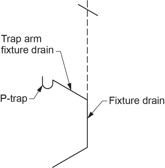
A fixture drain is the section of drainage pipe between the outlet of a single fixture trap and another section of the drainage system, such as another fixture drain, a branch, or a stack. In Figure 3, the trap arm section is called a “trap arm fixture drain” because it falls under both definitions.
Branch
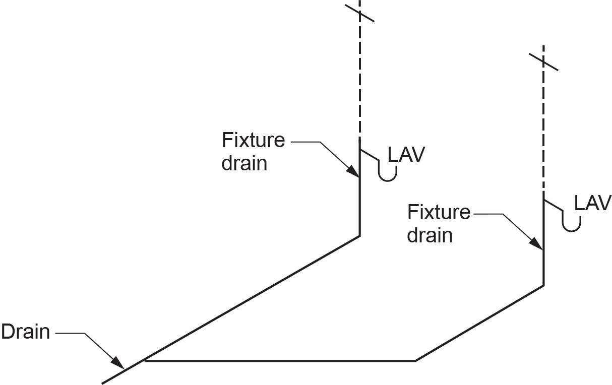
A branch in a drainage system is a sanitary drainage pipe that serves at least two fixtures located on a single storey and will connect at its downstream end to a stack, building drain, another branch, or possibly a sewage sump (Figure 4). The upstream end of a branch will connect two trap arms or fixture drains. A branch could also connect a stack to a building drain in the case where multiple stacks are installed in a building.
Stack
If a fixture drain or a branch carries waste through at least one storey, it is re-labeled as a stack. At its base, it will drain into either a branch or sanitary building drain, and it must have a cleanout near its lowest vertical point. The NPC also states that it must have a vent connected to the top of it, called a stack vent.
Wastewater flows through vertical pipes much differently than it does through nominally horizontal pipes. In order to understand the code requirements for piping connections at or near the base of stacks, a plumber must be aware of the pneumatic and hydraulic forces present in stacks.
Flow from a branch or fixture drain empties into the vertical stack using a wye and 45° fitting combination or a short-turn sanitary tee. When a high inflow rate is present, a slug of water is produced as the flow moves from horizontal to vertical (Figure 5). As the amount of inflow from the branch determines the size of the slug, there are limitations to the amount of flow entering the stack from any one floor level. This ensures discharge from the branch does not cause excessive interference with the sheet of liquid that may be flowing down the stack from above.
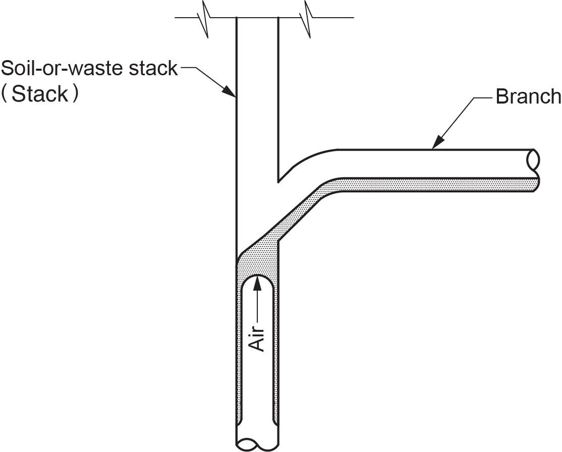
This slug is immediately accelerated at the rate of 9.8 m/sec/sec (32.2 ft/sec/sec) by the force of gravity. In a very short distance, air in the stack forces its way through this slug, sending the flow to the inner walls of the stack. This sheet of water — with a core of air in the centre — continues to accelerate until the frictional force exerted by the pipe wall on the falling sheet of water equals the gravitational force. The sheet of water will fall at a velocity that remains constant, provided that no additional flow enters the stack. This constant vertical velocity is called “terminal velocity,” and the distance within which this maximum velocity is achieved is called the “terminal length.” Field measurements have shown that a terminal velocity of 3–4.5 m/s (10–15 fps) is achieved within approximately 3–4.5 m (10–15 ft) from the point of entry to the stack. This constant velocity fact abolishes the myth that water falling from a great height will destroy the fittings at the base of a stack. In reality, the velocity at the base of an 80-storey stack is only slightly and insignificantly greater than the velocity at the base of a four-storey stack.
As the liquid falls down the stack, it exerts a frictional drag on the centre air core, dragging air with it. The air dragged downward is replenished by the stack vent to ensure negative pressures do not develop in the stack. The air being dragged down the stack can also cause positive pressure to build at the base of the stack. Therefore, the NPC requires that a vent stack be installed to serve any stack that conveys sewage through more than four storeys. The vent stack acts as a relief point for the air pressure created by the flow conditions at the base of the stack.
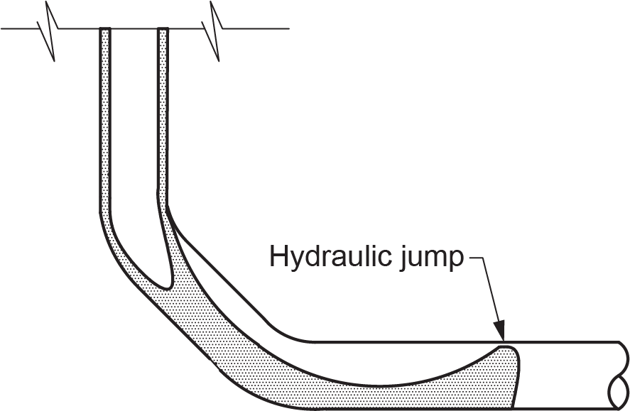
At the base of the vertical stack, flow enters the horizontal branch or building drain at stack terminal velocity. The velocity of the water flowing in the horizontal drain slowly decreases with a corresponding increase in the depth. This increase in depth is often great enough to completely fill the cross-sectional area of the pipe. This phenomenon of sudden rise in depth causes turbulence at the base of the stack and is called “hydraulic jump” (Figure 6).
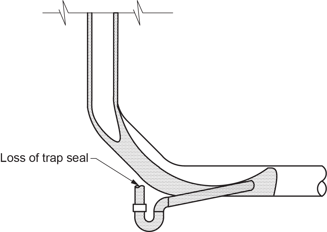
The turbulence resulting from hydraulic jump increases the static pressure, which can cause loss of trap seals in the downstream piping if the traps are installed too close to the base of the stack (Figure 7). The code requires that, in certain circumstances, fixture drains or branches be prohibited from connecting to a branch or sanitary building drain within 1.5 m (5 ft) of the bottom of the stack.
Sanitary Building Drain
A sanitary building drain is always connected to a sanitary building sewer at its downstream end. Its path takes it to the most upstream stack, branch, or fixture drain that has a toilet draining through it. It becomes the main horizontal sanitary collection pipe within the building.
A cleanout must be installed on the sanitary building drain to serve the sanitary building sewer. The cleanout should always be installed as close as possible to where the building drain leaves the building — either inside or outside — and be accessible for sewer cleaning equipment. Some municipalities require backwater valves to be installed on the sanitary building drain to isolate the entire building in the event of sewer backup.
Sanitary Building Sewer
The sanitary building sewer is the part of the drainage system that extends from the end of the building drain (1 m/39 in. outside the building) and conveys its discharge to a public sewer, private sewer, on-site wastewater disposal system, or other points of disposal. Building sewers often have additional cleanouts between the building wall and the main sewer. The cleanout is usually a minimum size of 100 mm (4 in.) in diameter with a water- and gas-tight cap.
Building sewers are commonly constructed using sewer-grade thin wall piping, although DWV grade is also acceptable. The pipes in a sewer are installed over a compacted bed of sand that supports them, preventing them from settling and losing their grade. Typically, plumbers lay the sewer from the foundation wall to the property line, and the municipal sewer crew is in charge of the installation from the property line to the sewer main.
Sewage Sump Basins
A sewage sump basin is used when plumbing fixtures are installed at a lower elevation than the gravity building drain. Although not defined in the plumbing code, this type of arrangement is known in the industry as a “sub-drainage system.” When used, the sewage is lifted into the building’s gravity drainage system by automatic pump equipment.
A sewage sump basin must be airtight to prevent the escape of gases generated by sanitary waste from the sub-drainage system. Since it is airtight, a vent is required to relieve the air in the basin as wastes discharge into it and also to supply air to the basin while the contents are being pumped to the sanitary gravity drainage system.
The NPC requires that the minimum size of the vent pipe for a sewage sump shall be one size smaller than the size of the largest branch or fixture drain draining to the sump. This required vent shall be not less than 2 in. (50 mm) and not greater than 4 in. (100 mm).
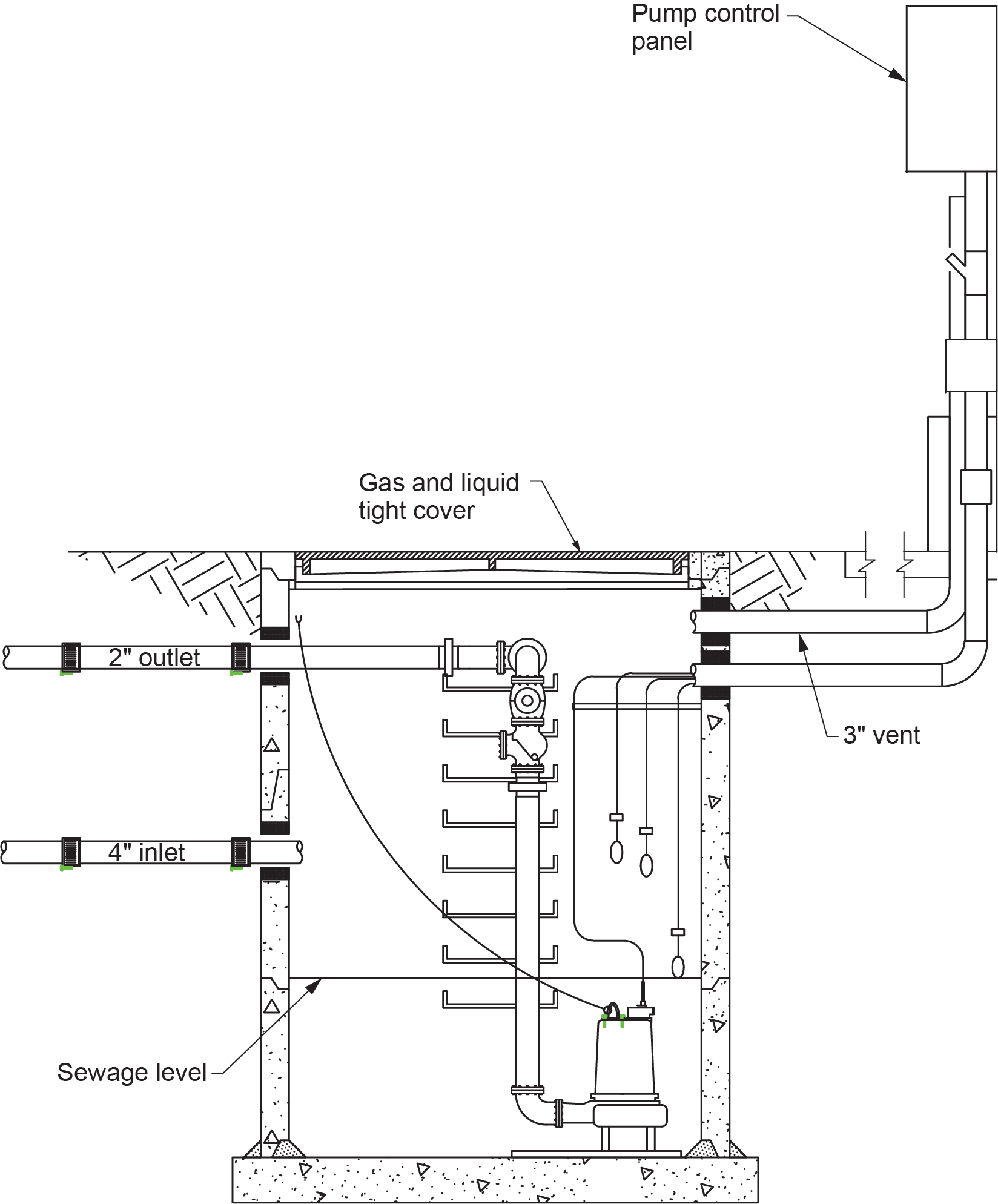
As with all mechanical devices, equipment failure can occur, resulting in flooding at the pumping basin. Commercial installations reduce this risk by installing two pumps (duplex) in a duty/standby configuration, with each pump capable of handling peak flow. If pumping station capacity is based on two pumps operating in parallel, a third pump (triplex) is usually provided as a standby. Residential or other private pumping stations may be equipped with a single pump (simplex) (Figure 8), since the incoming sewage flow can easily be controlled by restricting the usage of facilities.
Cleanouts
Cleanouts provide access to all parts of the drainage system so that obstructions can be removed. They should be located at intervals that conform to Table 2.4.7.2 of the NPC. The term “rodding” is an old term referring to the use of short pieces or “rods” of bamboo or similar material. These were coupled end-to-end and pushed into the drain to clear blockages. Because they did not bend easily around corners, there had to be many cleanouts installed, especially if the piping changed direction. Today’s modern drain “snakes” are made from coils of spring steel and are capable of long lengths and tight turns, so distances between cleanouts are much greater than were previously allowed.
Cleanouts range from removable plugs in wyes installed in horizontal drainage piping to manhole covers in building sewers. One-way rodding means using a wye as a cleanout, while two-way rodding would be using a line cleanout or a manhole as the opening in the piping. If line cleanouts or manholes are used, the allowable distance between cleanouts doubles over what could be achieved when using wyes.
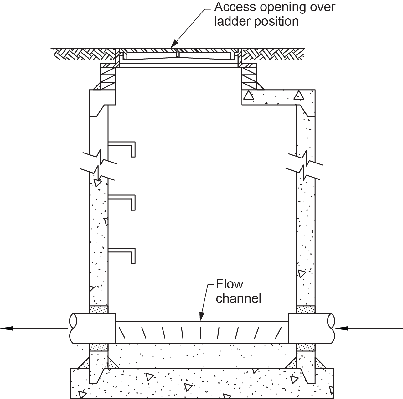
Manholes (Figure 9) are used as a cleanout for underground piping that is 200 mm (8 in.) or larger in diameter. They are constructed with metal covers of sufficient weight and strength for traffic and loading conditions. To direct flow through the manhole from the inlet pipe to the outlet pipe, a poured concrete channel — sometimes called “benching” — is used. It is shaped like a half-pipe. This channel is left open on top to allow access to the sanitary piping when required. To meet the applicable codes, manholes must be vented to open air if installed inside a building.
Vents
Vent piping allows the admission or emission of air into the system, limiting the pressure differential on the trap seals to not more than 1 in. WC (250 Pa). Venting lessens the likelihood of the removal of the water trap seals that serve the fixtures.
There are a variety of vents used in different applications. Common vents used include:
- Individual vents
- Dual vents
- Continuous vents
- Circuit vents
- Relief vents
- Additional circuit vents
- Offset relief vents
- Sump vents
- Branch vents
- Stack vents
- Vent stacks
- Vent headers
Individual Vents
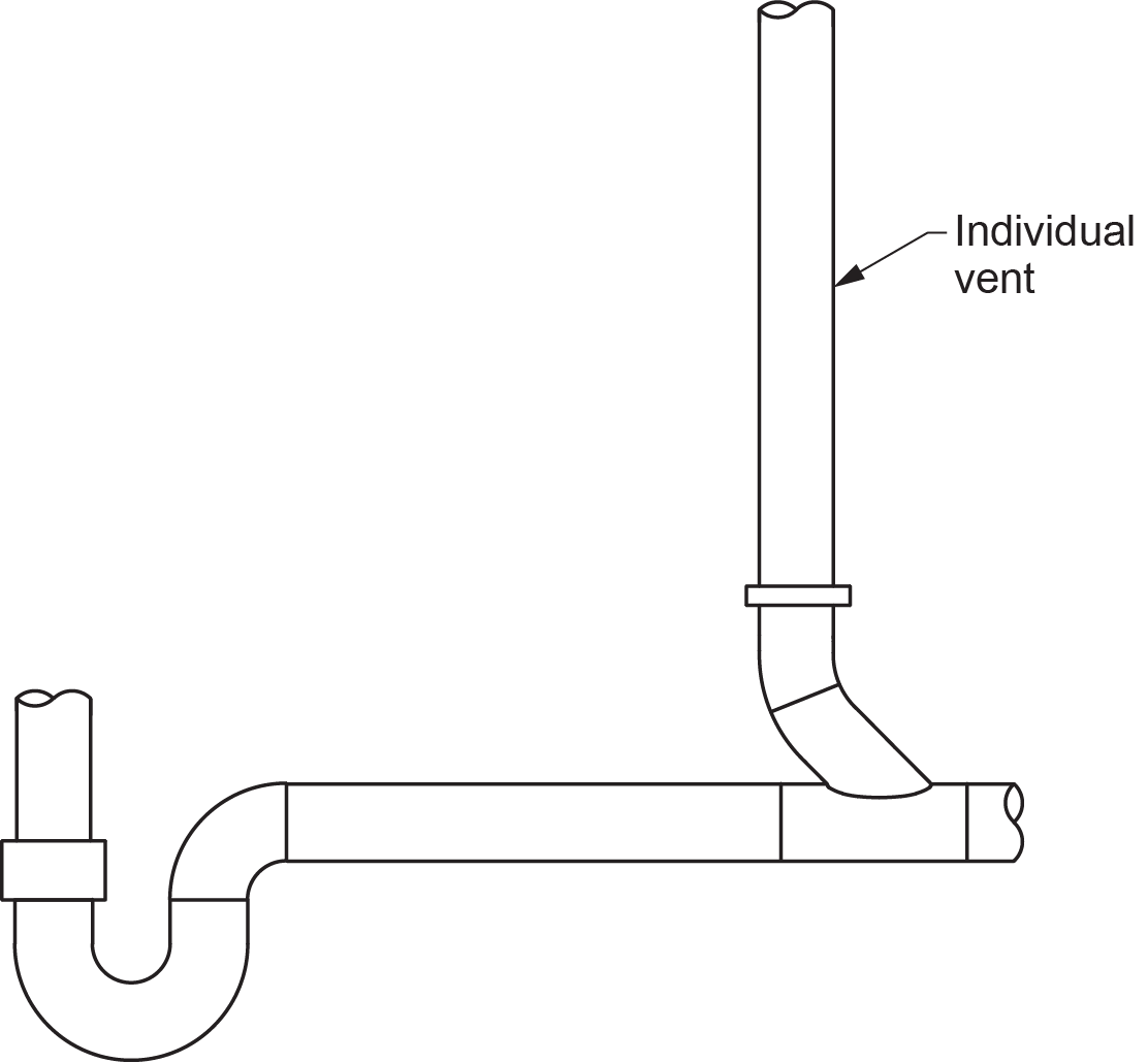
An individual vent is a vent that serves one fixture only and is connected to its horizontal trap arm (Figure 10). The vent must be installed into the trap arm in a nominally vertical orientation. Individual vents may extend from the fixture being served to the outside air without joining another part of the venting system, or they may connect into another vent that will eventually extend to the open air.
Dual Vents
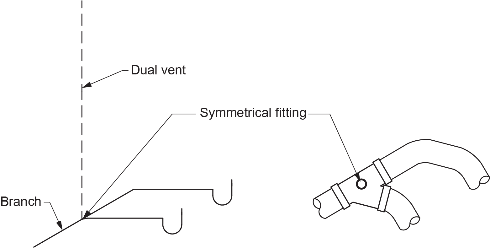
Dual vents are similar in many ways to individual vents but with one main difference: dual vents serve two fixtures as opposed to one. When connecting the two fixtures to the branch, a double symmetrical fitting must be used (Figure 11).
Continuous Vents
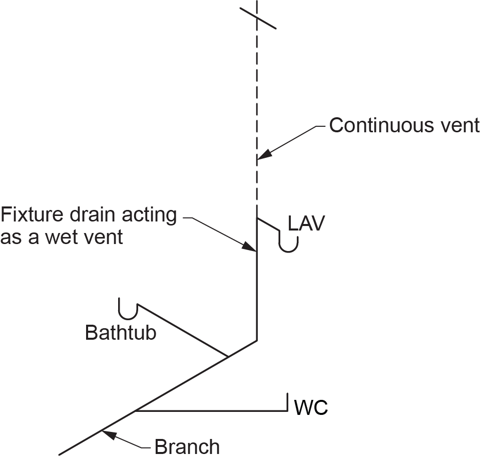
A continuous vent is a vent that extends from a vertical sanitary drainage pipe and can serve one or multiple fixtures located on the same storey. The most common application of continuous vents is to serve wet-vented branches (Figure 12). It may be important to remember that a continuous vent that is not also either an individual or dual vent will always be connected to either a fixture drain/wet vent or a branch/wet vent.
The naming of continuous vents overlaps with individual vents and dual vents if they are connected to a vertical sanitary drainage pipe, but the sizing requirements are different.
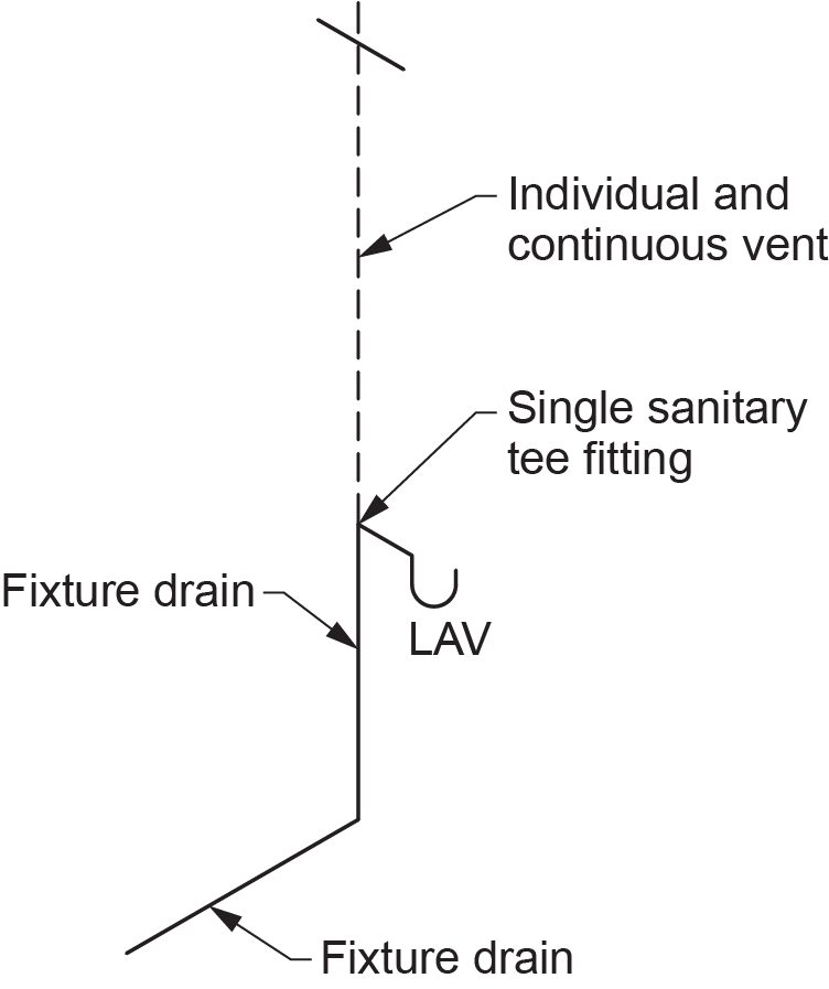
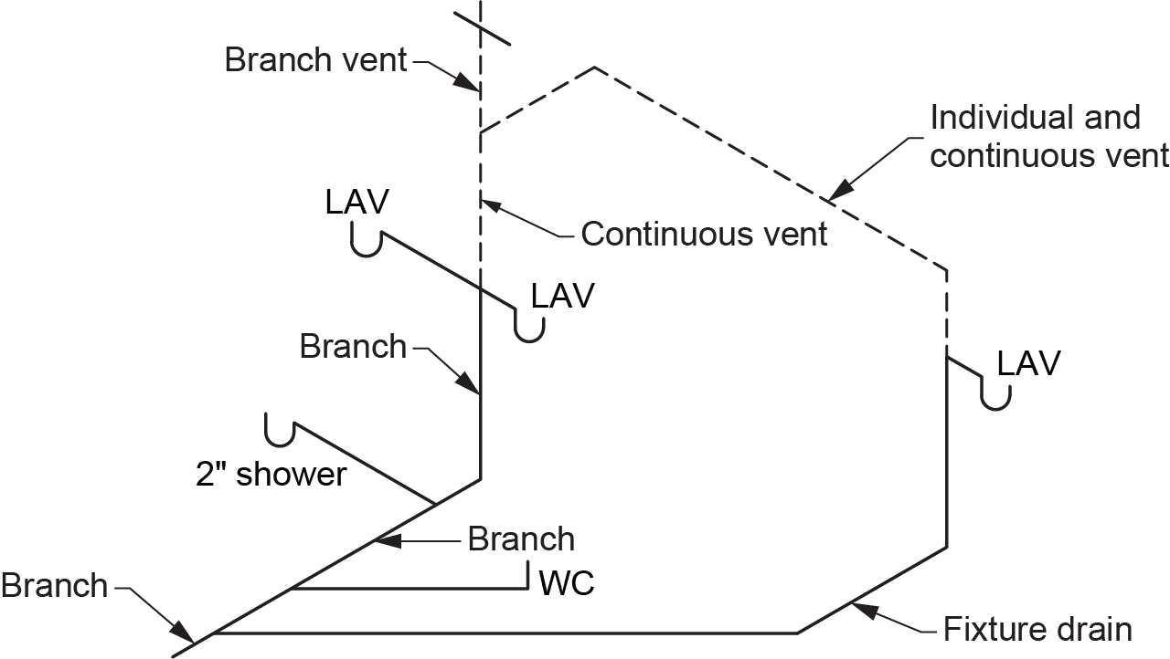
Individual and continuous vents (Figure 13) serve a single fixture connected to a vertical sanitary drainage pipe using a single sanitary tee.
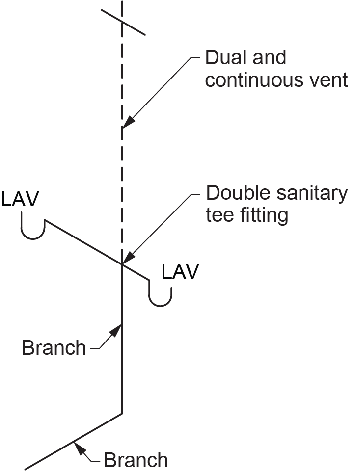
Dual and continuous vents (Figure 14) serve two fixtures connected to a vertical sanitary drainage pipe at the same level using a double sanitary tee.
Circuit Vents
Circuit venting is a method of commonly venting multiples of floor-outlet fixtures, most notably toilets. Circuit vents are typically used when serving a battery of fixtures with traps of 50 mm (2 in.) or larger in size (Figure 15). This configuration can also be used with 32–38 mm ([latex]1\tfrac{1}{4}[/latex]–[latex]1\tfrac{1}{2}[/latex] in.) traps, but it must comply with certain code requirements related to circuit venting these small traps. Circuit vents are connected to the trap arm of the most upstream fixture of the battery. Once connected, the circuit vent is extended upward to the open air or tied into another vent that extends to open air.
Relief Vents
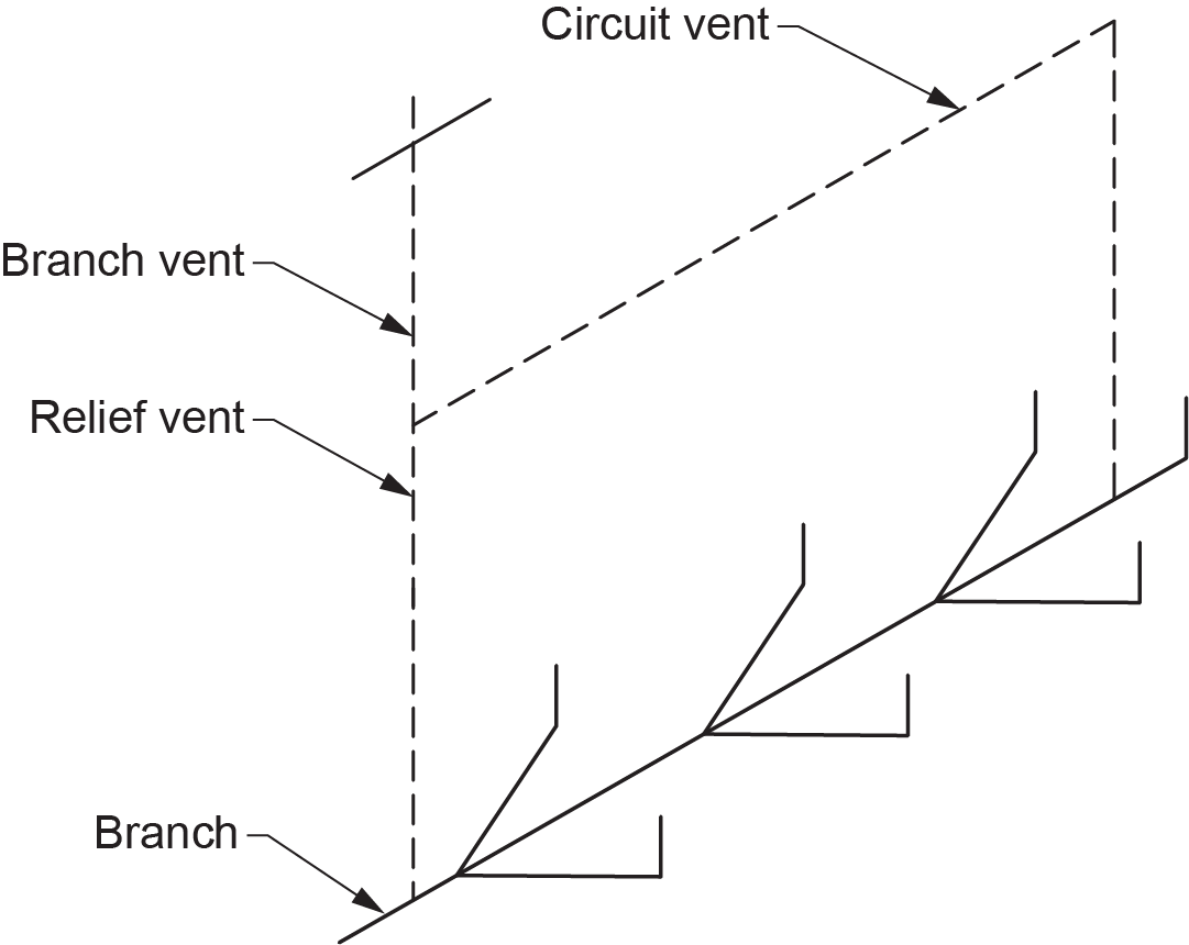
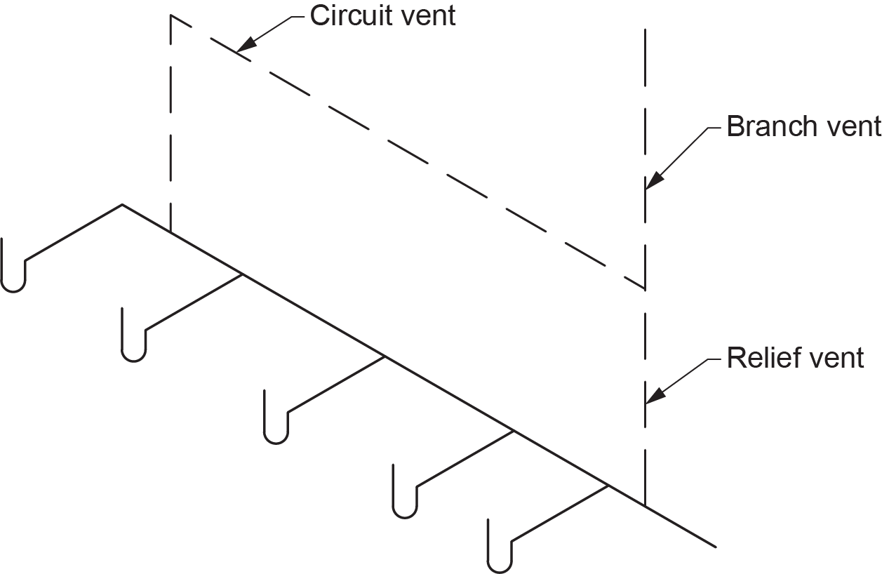
Relief vents are required for circuit-vented branches to assist with air circulation and relieve pressure fluctuations caused by fluid flow in the branch (Figure 16). A relief vent may also be a fixture drain, a branch, or even a stack. When these drainage pipes are used as a relief vent, they are limited in the number of fixture units that can be drained into them.
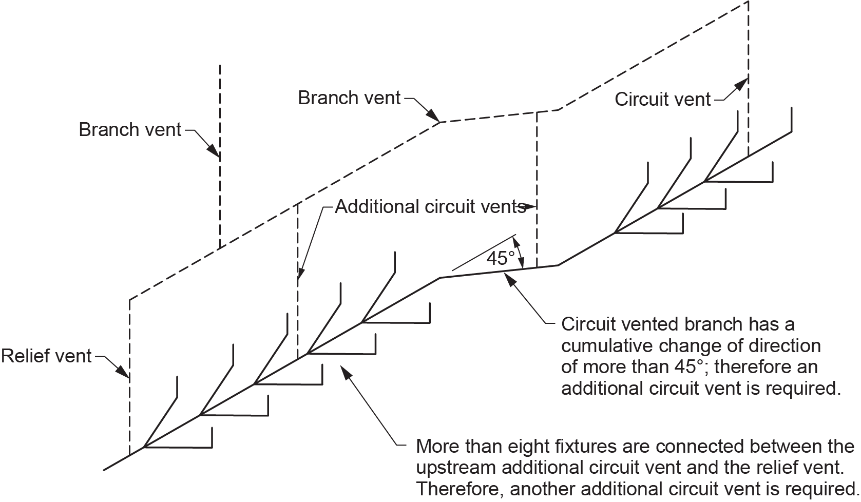
Additional Circuit Vents
Additional circuit vents (Figure 17) are required on circuit-vented branches when there are more than eight fixtures connected between vent pipes or there is a cumulative change in direction of more than 45° between the circuit vent and relief vent.
Offset Relief Vents
Offset relief vents provide additional air circulation to a stack with a nominally horizontal offset (Figure 18). An offset relief vent is required at A and B or A and C.
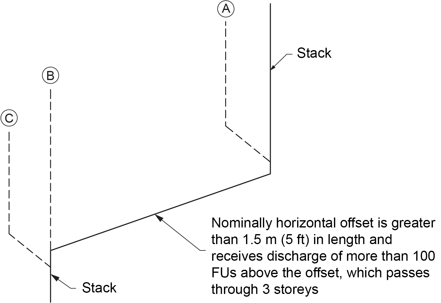
These vents are required if the offset is more than 1.5 m (60 in.) long and the upper portion of the stack passes through three or more storeys and has more than 100 fixture units on it. The offset relief vent connects at the lowest end of the upper stack after the last sanitary drainage pipe connection and at the upper end of the lower stack at a point higher than any drain connections.
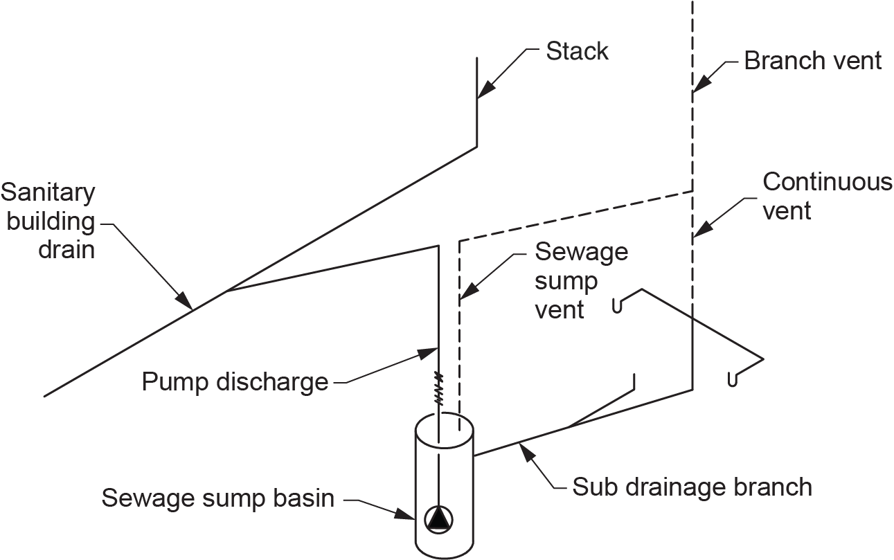
Sump Vents
A sump vent (Figure 19) serves the sewage sump basin only to ensure that the basin operates at atmospheric pressure. It is not associated with venting the fixtures draining into the basin, which are vented normally even though they are connected to a sub-drainage system.
Branch Vents
A branch vent is formed by combining two or more vent pipes that are not stack vents or vent stacks (Figure 20). Due to the hierarchy when naming vents, only some types of vents will become branch vents when tied into other vents.
Stack Vents
A stack vent is the main vent for the stack. It begins at the highest fixture connection to the stack and typically extends through the roof. It may also connect to a vent stack or another stack vent, which would form a vent header. It reaches open air either independently or through the vent header. The stack vent must be adequately sized to accommodate the necessary air flow created by the potential total liquid flow into the stack.
Vent Stacks
A vent stack protects the base of the stack by relieving the positive air pressures that accumulate from the air being dragged down the stack. The most effective connection point for the vent stack is at or immediately below the lowest vertical drainage connection to the stack. It is at this location that the pressure in the stack is at its maximum. Vent stacks are required when the stack has fixtures draining into it from more than four storeys. As with the stack vent, it must be adequately sized to accommodate the potential maximum flow at the base of the stack. Wet-vented stacks are exempt from this requirement as the increased wet vent size negates any positive pressure accumulation at the stack base.
Vent Headers
The vent header is the “king of the castle” in a venting system and always leads to outside air. Although a vent header is really not much different from a stack vent, it is named so that it can be sized by different rules. A vent header is the name of the pipe that results from two or more stack vents or vent stacks or any combination of these being joined (Figure 21). Once a vent pipe is named a vent header, connecting anything else to it will not change the name:
- stack vent + stack vent = vent header
- vent stack + vent stack = vent header
- stack vent + vent stack = vent header
Vent Hierarchy
As stated earlier, there is a hierarchy when naming plumbing vents. The importance of a vent’s role in the DWV system will determine not only its name but also when that name changes when connected to another vent type. It is very important to be able to identify the vents used in order to properly size them to code requirements. For example, if two individual vents are connected together, the resulting pipe becomes a branch vent. That single vent would be called a branch vent until it is connected to a higher class of vent — such as a vent stack, stack vent, or vent header — or until it terminates in open air. The first step is to understand that vents can be grouped into four categories, depending on their importance to the total system, as shown in Table 1. Note that Category 1 is the least important and Category 4 is the most important.
| Category 1 | Category 2 | Category 3 | Category 4 |
|---|---|---|---|
| Individual vent Dual vent Continuous vent Individual and continuous vent Dual and continuous vent Circuit vent Relief vent Additional circuit vent Sewage sump vent |
Branch vent | Stack vent Vent stack |
Vent header |
Once a vent has been categorized, its name will follow the hierarchy rules for venting. Refer to the vent pyramid in Figure 22 to help you understand how to identify the vent names.
Vent header (Category 4): created by connecting at least two Category 3 vents together (stack vents or vent stacks). Although a vent header is similar to a Category 3 vent, it is named differently so that it can be sized by a different code table.
Stack vent (Category 3): the vent at the top of a stack. It will remain a stack vent to open air unless it is connected to another stack vent or vent stack to form a vent header.
Vent stack (Category 3): a vertical vent pipe installed parallel to the stack and connected at its base. It will remain a vent stack to open air unless it is connected to another stack vent or vent stack to form a vent header.
Branch vent (Category 2): formed by joining two Category 1 vent pipes together. It will stay a branch vent until it is connected to a higher class of vent — such as a vent stack, stack vent or vent header — or it is terminated in open air.
Individual vent (Category 1): a vent that serves only one fixture and is connected at its lower end to the horizontal trap arm. The upper end may connect to a Category 2, 3, or 4 vent or terminate in open air.
Dual vent (Category 1): a vent that serves two fixtures. It connects with a double fitting where the horizontal trap arms meet to become a branch. The upper end may connect to a Category 2, 3, or 4 vent or terminate in open air.
Continuous vent (Category 1): a vent that extends from a vertical branch/wet vent or fixture drain/wet vent and can serve multiple fixtures located on the same storey. The upper end may connect to a Category 2, 3, or 4 vent or terminate in open air.
Individual and continuous vent (Category 1): a vent that serves only one fixture and is connected at its lower end to the junction of a vertical fixture drain and a horizontal trap arm. The upper end may connect to a Category 2, 3, or 4 vent or terminate in open air. The naming of this vent combines two of its attributes. Because it is an extension of a vertical fixture drain, it is a continuous vent, and because it serves only one fixture, it is an individual vent.
Dual and continuous vent (Category 1): a vent that serves two fixtures and is connected at its lower end to the junction of a vertical branch and two symmetrically connected trap arms. The upper end may connect to a Category 2, 3, or 4 vent or terminate in open air. Similar to the individual and continuous vent, the naming of this vent combines two code definitions. Because it is an extension of a vertical branch, it is a continuous vent, and because it serves two fixtures connected at the junction of the trap arms, it is a dual vent.
Circuit vent (Category 1): A vent that serves multiple fixtures on a horizontal branch installed on the same storey. Its lower end is connected to the trap arm of the most upstream circuit vented fixture on the branch. The upper end may connect to a Category 2, 3, or 4 vent or terminate in open air. Circuit vents must always be paired with a relief vent located downstream of the most downstream circuit vented fixture and may also require an additional circuit vent.
Relief vent (Category 1): required for circuit vented branches to assist with air circulation in the branch. The lower end of the relief vent is connected to the circuit vented branch downstream of the most downstream circuit vented fixture. The upper end of the relief vent may connect to a Category 2, 3, or 4 vent or terminate in open air.
Additional circuit vent (Category 1): required on circuit vented branches if there are more than eight trap arms or a cumulative change in direction of more than 45° between the circuit and relief vent. The lower end of the additional circuit vent is connected to the circuit vented branch in the offset piping or between fixtures to limit the number of circuit vented fixtures between any two vent pipes to eight. The upper end of an additional circuit vent may connect to a Category 2, 3, or 4 vent or terminate in open air.
Sump vent (Category 1): The NPC requires that sewage sumps be watertight, airtight, and vented. The vent allows sewer gas to travel to open air, where it dissipates. Another purpose of the vent is to allow air to enter the sump when the liquid level drops during pump operation. The lower end of the vent attaches to the sump cover, while the upper end may connect to a Category 2, 3, or 4 vent or terminate in open air.
 Self-Test D-1.3 Functions of Different Pipes in a DWV System
Complete Self-Test D-1.3 and check your answers.
If you are using a printed copy, please find Self-Test D-1.3 and Answer Key at the end of this section. If you prefer, you can scan the QR code with your digital device to go directly to the interactive Self-Test.

References
Skilled Trades BC. (2021). Book 2: Install fixtures and appliances, install sanitary and storm drainage systems. Plumber apprenticeship program level 2 book 2 (Harmonized). Crown Publications: King’s Printer for British Columbia.
Trades Training BC. (2021). D-1: Install sanitary drain, water and vent systems. In: Plumber Apprenticeship Program: Level 2. Industry Training Authority, BC.
Media Attributions
All figures are used with permission from Skilled Trades BC (2021) unless otherwise noted.
