D-1.11 Trade Waste Systems
Provincial and federal plumbing codes have been developed with a focus primarily on the conveyance of liquid waste generated by domestic plumbing fixtures, such as toilets, basins, bathtubs/showers, kitchen sinks, and laundries. When used in a residential settings, these fixtures normally have a discharge with little fats, oils, grease (“FOGs”), and other constituents that may have a negative impact on the private or municipal sewage system to which they are connected. As such, they are routinely drained directly into such systems without needing any pre-treatment.
Establishments other than residential occupancies may be required to install special piping arrangements and pre-treatment systems, known as trade waste systems, when deemed necessary by the authority having jurisdiction (AHJ). Trade waste is sewage that may be of significantly increased organic strength compared to domestic sewage and may also contain other substances, such as high levels of fats and grease, heavy metals, organic solvents, and chlorinated organic substances. These pollutants can harm people, the environment, and the wastewater system; they are removed by installing some form of interceptor. As well, some commercial and industrial processes may wish to reclaim valuable constituents, such as silver in photo finishing labs, that may otherwise be lost through the drainage system.
An interceptor is defined in the National and BC Plumbing Codes as “a receptacle that is installed to prevent oil, grease, sand or other materials from passing into a drainage system.” Interceptors come in a variety of types and sizes and are typically a manufactured item; however, they can also be constructed on-site, such as a concrete sump or catch basin for stormwater systems (covered in this textbook’s section on storm drainage systems).
Many plumbing professionals of an “older vintage” may remember what trade waste systems are and why they may be necessary, but definitions for trade waste systems are no longer included within current versions of either the National Plumbing Code of Canada or the BC Plumbing Code. One would have to look back to the 2007 version of the BC Plumbing Code to find the last regulatory definition for a trade waste system, which is as follows:
Trade waste system means a system of drainage pipes from floor drains and hub drains located in food display areas that are intercepted by a trade waste sump and backwater valve before entering the sanitary building drain.
Another definition for trade waste can found in a reference from a current regulation in Auckland, New Zealand, which reads:
Liquid trade waste is any discharge to a sewerage system other than domestic waste from a hand wash basin, shower, bath or toilet.
Yet another reference is found within a current publication from the locality of Victoria, Australia:
Trade waste is any water that goes down the drain that has been used in a commercial environment for food preparation, cooking, cleaning dishes or cleaning the kitchen area.
Regardless of the origin or jurisdiction of the definition, the intent seems clear: any discharge into a sewage system from fixtures or appurtenances other than those found in a residential setting may be referred to as “trade waste” and may therefore require special consideration by the AHJ and the installer.
Cities and municipalities are empowered under the provincial Environmental Management Act to regulate the discharge of waste into their sewers. As well, although not specifically mentioned in our federal and provincial plumbing codes, the requirement for a trade waste system can be interpreted from those codes in Clause 2.4.4.1.(1) “Sewage Treatment,” which states:
Where a fixture or equipment discharges sewage or waste that may damage or impair the sanitary drainage system or the functioning of a public or private sewage disposal system, provision shall be made for treatment of the sewage or waste before it is discharged to the sanitary drainage system.
This means that the undesirable component(s) within the discharge must be either removed or rendered harmless to the system downstream. This would involve using some type of interceptor.
Grease Interceptors
There is some confusion in the field over the use of the terms “grease trap” and “grease interceptor.” In the United States, their two main model codes have, in the past, determined that the use of the two terms was dependent upon the flow rates or maximum capacities involved. In Canada, we make no such distinctions, and the terms are synonymous, meaning that they both refer to the same piece of equipment. A grease interceptor cannot be used as a trap for the fixture feeding it unless it can be proven that the interceptor can provide a minimum 38 mm ([latex]1\tfrac{1}{2}[/latex] in.) trap seal. In most cases, this is difficult to prove, so any fixture draining into the grease interceptor will need its own trap. As well, if the interceptor qualifies as a trap, then it will have to be placed within 1,200 mm (4 ft) of the furthest outlet on the sink that feeds it, in order to comply with Clause 2.4.8.2.(1) in the code (NPC, 2020, B 2-30).
The most common type of trade waste system found in the field is a “passive” or “hydromechanical” grease interceptor serving a commercial pot sink or similar type of fixture. These systems are commonly required in any commercial kitchens that cook food on site, such as restaurants and fast food outlets. Only the grease-handling fixtures will be piped into the grease interceptor. This allows for more accurate sizing and cost effectiveness.
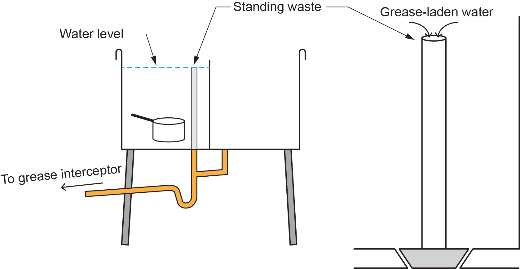
In a commercial kitchen, greasy pots and pans are submerged in a compartment of a pot sink that has a standing waste inserted into its drain opening. A slow supply of hot water is allowed to constantly run into the sink compartment. The resulting grease-laden water spills into the top of the standing waste and is directed via the sink’s outlet piping to a grease interceptor.
Grease Interceptor Operation
It is a popular misconception that grease interceptors work best if the grease-laden discharge entering the interceptor is as cool as possible. This only serves to plug the inlet piping with grease that has come out of solution too soon. Rather, interceptors function best if the incoming fluid is kept as hot as possible. This allows the grease to separate, cool, and solidify inside the interceptor, where it can be stored until manually removed by hand or, more commonly, cleaned out on a regular interval by companies that use “jet vac” trucks. Also, keeping the interceptor as close as possible to the fixture feeding it ensures the water stays as hot as possible. A flow control fitting installed on the inlet piping or within the interceptor at its inlet ensures that the flow rate through the interceptor is kept to design limits and turbulence within the interceptor is kept to a minimum, which enhances its operation.
Most plumbing codes require a cleanout be installed immediately downstream of any grease interceptor, due to the probability that some grease will make its way through the unit and, over time, clog the piping.
Operationally, it is suggested to use as little detergent as possible. Soaps and detergents act to break down the fats, oils, and greases (FOGs) into much smaller particles that tend to move through the interceptor rather than rise and be trapped within it. This is problematic for all downstream piping as well as the treatment facility at the end of the system.
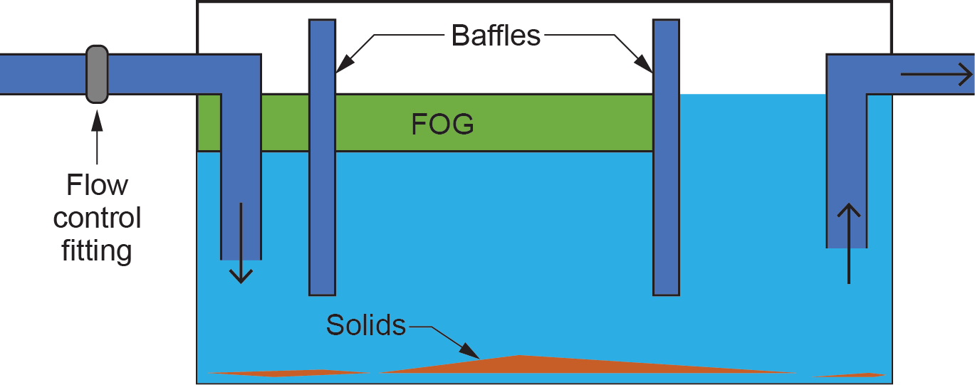
Grease interceptors are boxes constructed of stainless steel, plastic, or epoxy-coated steel. Wastewater or effluent enters the interceptor and fills the tank. A system of baffles may be used to slow down water and allow FOGs to cool and effectively separate. Solids settle or sink and either accumulate at the bottom or, if small and light enough, are carried off through the outlet and usually do not pose problems downstream. Some models may have a strainer to catch solids, reducing the quantity settling in the bottom of the interceptor. FOGs, having a specific gravity less than water, float and accumulate at the top. Effluent siphons out the outlet to the downstream drainage system piping.
FOGs and solids sit in the interceptor until emptied (a task advised when the box is approximately 25% full). The stagnant waste can often lead to bad smells, an increased risk of pest infestation, and less-than-sanitary kitchens. Be aware that if passive grease interceptors are neglected, they will become ineffective as the tank fills with FOGs, and the drainage rate slows or stops.
Automatic Grease Interceptors
Automatic grease interceptors are often considered a more sophisticated grease removal system than the passive variety, with solids and grease being separated from grey water into collection containers ready for daily disposal.
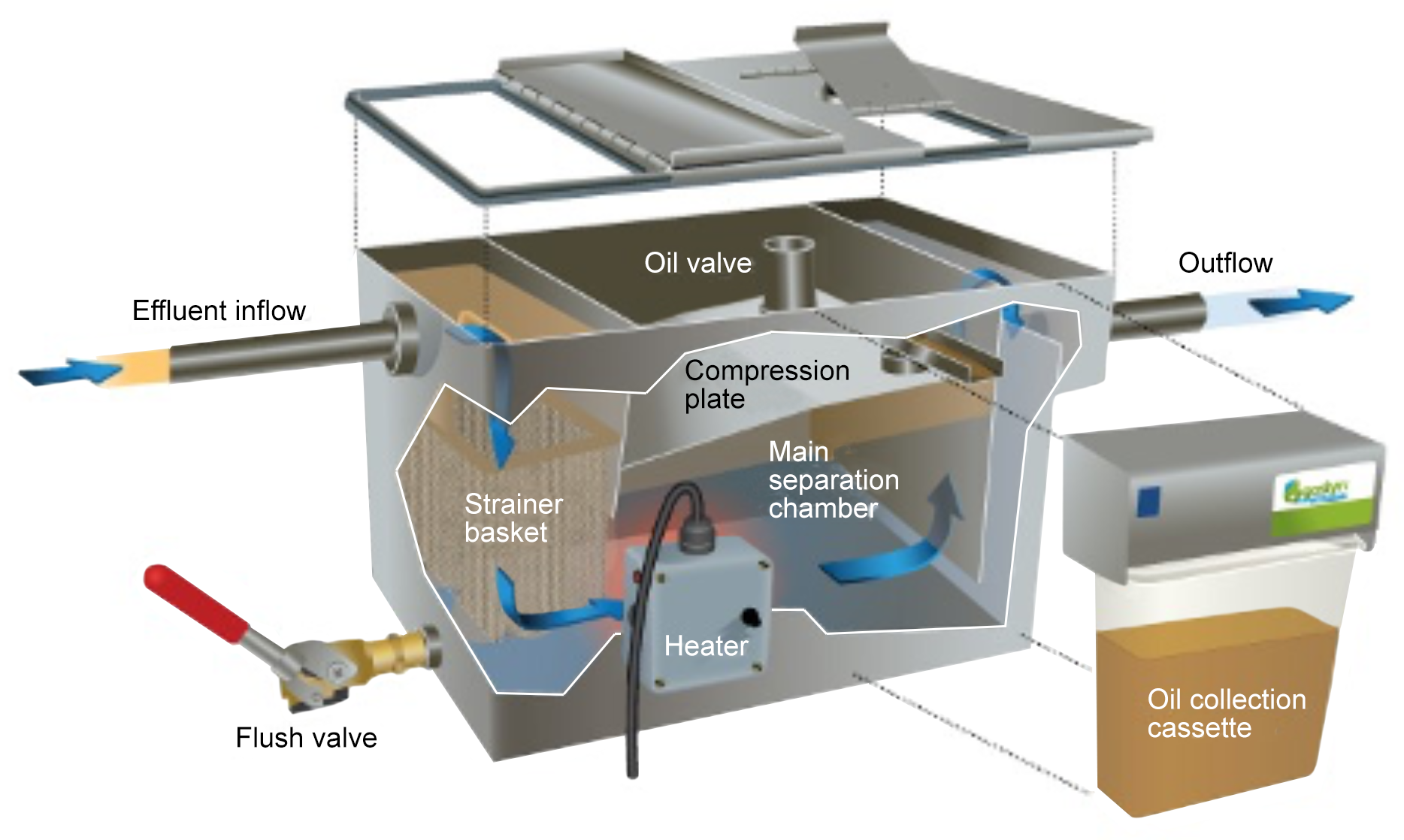
In an automatic grease interceptor, wastewater enters the grease trap and passes through a filter that collects solids. Water mixed with FOGs flows through to the main chamber. Non-mechanical grease recovery units employ a small heater that prevents FOGs from cooling and solidifying, using hydrostatic pressure to force FOGs out into an external oil container.
Automatic mechanical models allow FOGs to cool and separate to the surface (as with passive); however, they regularly skim the top layer into a separate collection container.
In either case, water continues the journey into the sewer via the outlet, unaccompanied by any unwanted additions. FOGs and solids are effectively separated into independent containers that can be easily disposed of by staff members without needing to shut the kitchen down and force down time. A major benefit of automatic grease separators is that they continuously remove FOGs to maintain the ongoing efficiency of the trap.
The addition of grease-busting enzymes to the waste entering interceptors is discouraged, as the now-minute particles of grease and fats move through the interceptor into the system downstream and become a problem there rather than being contained and removed within the interceptor.
Interceptors can be installed fully exposed on the floor, fully or semi-recessed into a floor, or located completely underground. The key point remains that they will need to be accessible for cleaning and servicing.
Sizing Grease Interceptors
Grease interceptors are sized according to the rate of incoming flow in US gallons per minute (USGPM). Associated with the incoming flow rate is an interceptor’s storage capacity. The rated capacity, in pounds (lb), is listed at twice the flow rate, in GPM. For example, a 10 GPM interceptor has a rated capacity of 20 lb of grease.
Example:
Suppose that a two-compartment commercial pot sink has compartments that measure 18 in. in length by 18 in. in width by 16 in. in depth. The two compartments will, therefore, have a capacity of [latex]18\times18\times16\times2= 0\,368\text{ in.}^3[/latex]. One US gallon (the typical unit of measure) is 231 in.3, which translates to a capacity of [latex]10\,368\div231=44.88\text{ USG}[/latex].
A common assumption in grease interceptor sizing methods is that a full sink in use will have roughly 25% of its volume taken up by pots, pans, and other items being washed, so [latex]44.88\times0.75=33.66[/latex] US gallons of grease-laden water to process. Industry-standard drain down time is expected to be one minute, so the correct interceptor to choose should have a flow rate of at least 33.66 GPM and will, therefore, have a storage capacity of approximately 67.3 lb of grease.
One would then consult manufacturers’ charts to select an appropriate model and size. When the desired flow rate falls between two model sizes, always defer to the larger size.
Interceptors are the intended terminus of unwanted materials being carried through any trade waste system, and there are many types to choose from. The following is an example list of interceptors that Watts Industries manufacture:
- Art rooms, dental labs, metal recovery: SI-742, SI-742-L, SI-762
- Commercial laundry, washing machines: LI-800
- Cooking, prep sinks, dishwasher: WD Series, GI-K Series
- Elevator pits & oil spill areas: OI Series, OI-K Series
- Hair wash sinks: SI-750, SI-750-TO
- Pot, pan, scullery sinks: WD Series, GI-K Series
- Sand and sediment: SA Series, See Also FD-410
- Catch basin vehicle and maintenance areas: OI Series, OI-K Series
Other Trade Waste Systems
Pot sinks draining into grease interceptors is an example of only one type of trade waste system. Figure 4 is an example of a trade waste system that might be found in a food processing plant. In essence, it is a type of circuit-vented system that is allowed to have flat dry vents as long as there are appropriately placed cleanouts installed.
The diagram above appeared in A-7.4.2.1.(5) of the appendix in the 2007 edition of the BC Plumbing Code but has not been published in the plumbing codes since. However, most plumbing officials are aware of its previous existence and intent and may refer to it when specifying to customers the mandated use of a trade waste system.
The following are the referenced clauses that accompanied the diagram in the appendix:
- This system is restricted to discharge only from product display cases, ice machines, cooler condensate, and emergency discharge from a heat reclaim pump.
- Hydraulic load for traps in trade waste systems should be:
- 3 FUs for a 3 in. trap
- 4 FUs for a 4 in. trap
- All drainage branches should be sloped at a minimum of a 1 in 50 slope for pipes up to 3 in. in diameter and 1 in 100 for 4 in. in diameter and over.
- Trap arms should have a downward slope in the direction of flow with a minimum of a 1 in 50 slope and shall not exceed the pipe diameter.
- Fixture outlet pipes should have a developed length not greater than 900 mm.
- A reduction of pipe size on a horizontal branch should leave a vent at the point of reduction.
- All vents should be not less than 1.5 in. in diameter
- Any dry vent should roll off the top of a horizontal waste pipe where possible.
- Heat reclaim trenches should be provided with an emergency pumped drain and an alarm system.
- Trade waste system sumps should be a minimum 24 in. square and up to 48 in. in depth. Larger sumps are required for greater depths. Sumps should have an 18 in. liquid depth and should be provided with a backwater valve at the outlet.
- Trade waste systems should be restricted to a single floor level.
As well, the two clauses below were included in the code reference above.
A-7.4.3.3.(1) Waste with Organic Solids. Equipment such as garbage grinders and potato peelers produce waste with organic solids. These devices reduce most waste into small- sized particles that will flow easily through the drainage system. However, if they are located upstream of the interceptor, the particles could block the interceptor.
The above clause still exists in both the BC and national codes, in 2.4.3.3 (1) and (2), but is a bit more definitive in that it prohibits any equipment discharging waste that contains organic solids from being installed upstream of a grease interceptor unless an organic solids interceptor is installed in between them.
A-7.4.4.3.(1) Grease Interceptors. Grease interceptors may be required when it is considered that the discharge of fats, oil or grease may impair the drainage system. Information on the design and sizing of grease interceptors can be found in ASPE Data Book, Volume 4, Chapter 8, Grease Interceptors.
The above clause has been replaced and expanded upon in the current codes. Clauses 2.4.4.3.(1), (2), (3), and (4) identify the code requirements for instances where a grease interceptor, oil interceptor, or interceptors for sand, grit, and other such materials must be installed. Any other locations or situations are left to the discretion of the authority having jurisdiction.
As well, Clauses 2.4.4.4.(1) and (2) of the current code editions spell out the requirements for the installation of neutralizing and dilution tanks for acid waste. These would also be considered a specific type of interceptor.
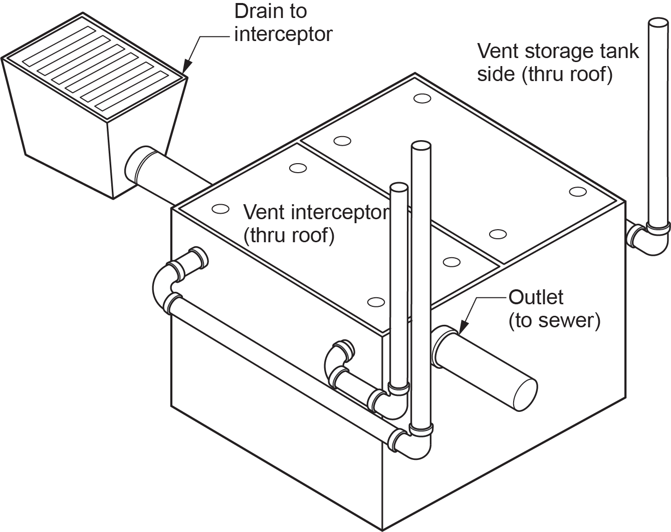
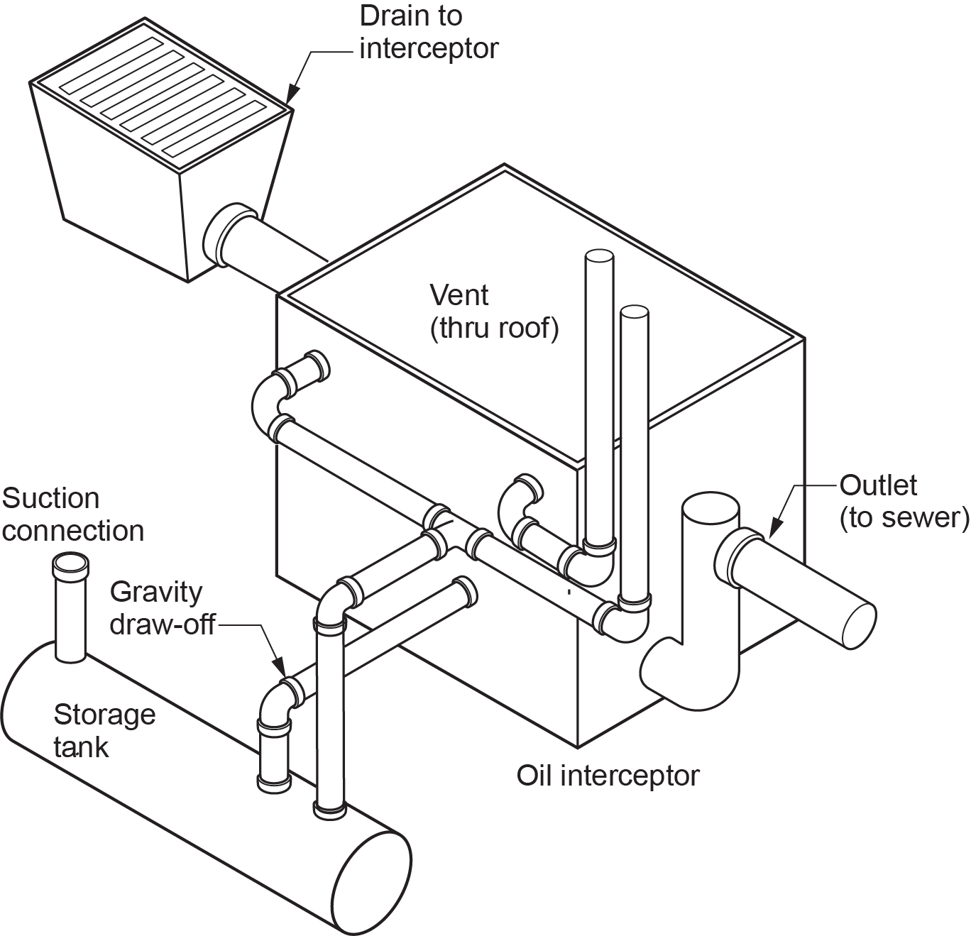
Oil Interceptors
Oil interceptors are designed for use in drain lines from areas where oils, sediment, and other liquids are found. These areas may be parking garages, machine shops, service stations, aircraft hangars, industrial and manufacturing facilities, etc., and all need an environmentally sensible way to be drained.
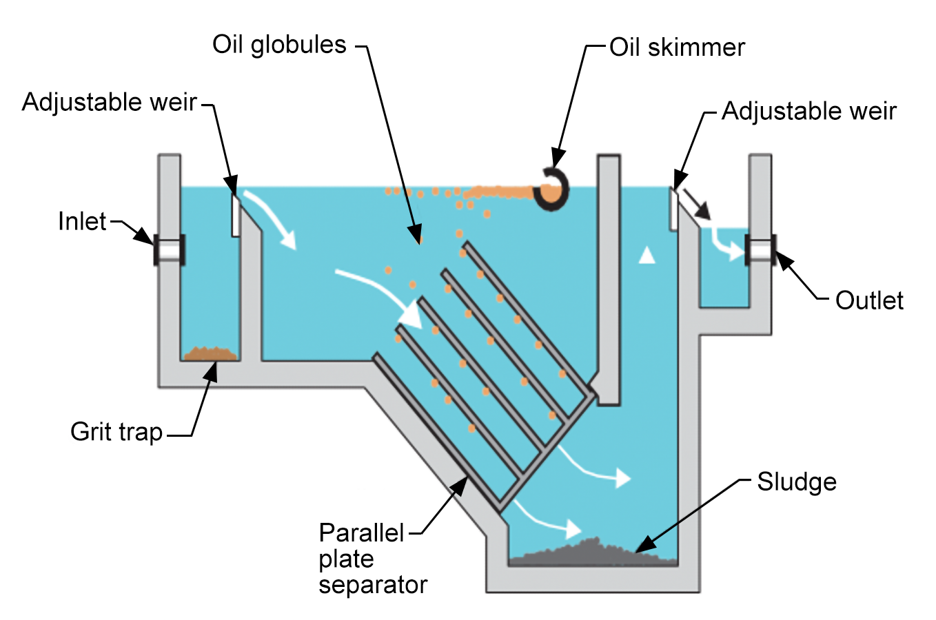
Operating an oil interceptor is very similar to that of a passive grease interceptor. The solid baffle plate opposite the inlet to the oil interceptor diffuses the flow into the interceptor and lessens the turbulence of the oil-laden water as it enters the intercepting chamber. Solids and sludge carried in the water are stopped by the baffle and collected in the solids retaining bucket between the inlet and the flow-retarding baffle. Such accumulation can then be removed. The resulting quiet, even flow of water through the interceptor permits the oils and other light density substances to rise to the surface by the “flotation” principle of separation. Oils are less dense than water; therefore, gravity causes the oil to float to the surface of the water. Maximum separation and interception is proportional to the elimination of turbulence of wastewater within the interceptor. The unique baffle/bucket design permits almost 90% of the interior of the interceptor to be used for oil separation.
Like in grease interceptors, oil interceptors are constructed of 100% epoxy-coated steel for long-lasting performance and durability.
Some models have an oil draw-off assembly that allows the separated oils and other similar light-density substances automatically drain out through a properly adjusted internal stand pipe. A pipe connection from the internal adjustable standpipe is connected to an oil drain line leading from the oil interceptor to an oil storage tank, which may be a component of the interceptor (Figure 7), or may be separate from the interceptor.
A standpipe sleeve (brass tube) within the oil containment compartment must be adjusted so the opening is [latex]\tfrac{1}{8}[/latex] in. above the top of the normal water flow level in the interceptor chamber. The oil that floats to the surface will drain off by gravity flow as waste water flows through the interceptor. When the adjustable sleeve in the standpipe is correctly set, no water will drain off with the oil, and there is no need to manually skim the oil.
Dilution and Neutralization Tanks
pH is a measure of the hydrogen ion (H+) concentration in a liquid and classifies liquids as being acidic or caustic. pH values range from 0 to 14 and indicate the degree of acidity or alkalinity of a liquid. A liquid with a pH value below 7 is acidic, and a liquid with a pH value above 7 is alkaline. A pH of 7 indicates that a liquid is neutral.
Liquid discharges that are either too acidic or too caustic may cause corrosion damage to downstream piping systems and may also adversely affect the environment or create problematic conditions for waste water treatment plants. It should be noted that acidic and caustic liquids can be equally harmful; hence they should be treated with equal attention. Chemical effluent should be treated to ensure that the pH level is as close to 7 as possible or to other values dictated by the authority having jurisdiction.
Generally, effluent with a pH range of 5.5 to 8.5 can be disposed of without treatment, but local requirements may vary and must be adhered to. However, even mild caustics and acids within this range can cause severe damage to piping systems, depending on the piping material. Therefore, it is recommended that the composition of piping materials is checked against both the predicted pH discharge level and the individual chemicals being discharged to ensure compatibility.
Neutralization
Neutralization is a chemical reaction resulting from the physical mixing or extended contact of a base and an acid to form a neutral solution of water and salt. This neutral solution is suitable for discharge into sanitary sewer systems. Neutralization is accomplished by one of three methods:
- Dilution
- Limestone chips (calcium carbonate)
- Chemical dosing
Dilution
Dilution involves physical mixing the chemical waste with water to stabilize (dilute) the waste. Initial dilution can be as simple as flushing the chemical with water at the sink and discharging the mixture through a p-trap and the associated drainage piping. Alternatively, dilution can be accomplished via a large dilution trap (dilution tank) located under the bench at each sink. In either case, the waste piping should discharge into a central neutralization system for further treatment prior to discharging into the sewer system.
Limestone Chip Neutralization
In a typical system, acidic waste is drained into a plastic tank filled with high purity limestone chips that are 1–3 in. in diameter with a calcium carbonate (CaCO3) content of at least 90%. After a designed dwell time in the tank, the chemical is neutralized and subsequently discharged by gravity flow into the sewer. The chemical reaction creates an off-gassing, and therefore, these tanks should be vented. The limestone is used up in the process and must be replaced periodically. Dilution and neutralization using limestone chips is most commonly used as a small-scale point-of-use treatment.
Note that an alkaline solution can be as corrosive and problematic to systems and piping as an acidic solution. An alkaline solution with a pH of more than 7 would require an acid to neutralize it and bring its pH level down to near 7.
Chemical-Dosing Neutralization Systems
Instead of using limestone chips for neutralization, chemicals can be injected into the waste stream to achieve the same result. Sophisticated controls monitor the process and introduce a solution of acid, base (alkali), or both into the chemical waste holding tank via metering pumps, controls, and mixers. The resulting liquid mixture chemically reacts to form a salt and water composition, which is then discharged by gravity flow into the sewer. These systems are usually installed in large buildings that contain laboratories and similar operations. The tanks can sometimes be as large in volume as a classroom.
Solid Interceptors
Solids interceptors are perhaps the least sophisticated variety of interceptor. They are designed to recover all types of solids from precious metal particles to food waste, plaster, clay, or similar materials. This is accomplished through the principle of gravity separation. Particles of various sizes and weights are trapped in a bucket. Some varieties of solids interceptors have a replaceable filter bag (similar to a vacuum cleaner) for ease of disposal.
The wastewater flows from the inlet piping into the removable bucket or filter bag, passes through a screen into the main body chamber, and then exits the interceptor to the sanitary drainage system. An example of a solids interceptor would be a hair trap installed on the fixture outlet piping from a beauty parlour sink.
Interceptor Venting
The venting of interceptors should conform to the manufacturers’ specifications but must also satisfy the requirements of the plumbing code. A-2.5.5.2 in the “Notes to Part 2” of the BC and National Plumbing Codes shows a graphic of suggested venting for an oil interceptor. The following are some examples of code requirements for venting sewage sumps, oil interceptors, and dilution tanks.
If a sewage sump is used as an interceptor, Clause 2.5.5.5.(1) states that it must be provided with a vent pipe connected to the top of the sump, and Article 2.5.7.7 states that it shall be a minimum size of one size smaller than the size of the largest branch or fixture drain connected to the sump and be at least 2 in. but need not be larger than 4 in.
Oil interceptors have many venting requirements found in Article 2.5.5.2, the most significant being that any vents from oil interceptors cannot be interconnected with other vents. They must extend independently to outside air and differ in elevations where they terminate.
Dilution tank venting requirements are found in Article 2.5.5.3 and 2.5.5.7 and are similar to those for venting sewage sumps.
Consult the applicable plumbing codes for the full scope of venting requirements for interceptors.
 Self-Test D-1.11: Trade Waste Systems
Complete Self-Test D-1.11 and check your answers.
If you are using a printed copy, please find Self-Test D-1.11 and Answer Key at the end of this section. If you prefer, you can scan the QR code with your digital device to go directly to the interactive Self-Test.

References
Skilled Trades BC. (2007). Figure A-7.4.2.1.(5): Trade waste system. In Vancouver Building By-law 2007 – Part 7: Plumbing Services (Appendix A). Retrieved January 20, 2025, from https://free.bcpublications.ca/civix/document/id/public/vbbl2007/building_B_appA_P7
Skilled Trades BC. (2021). Book 2: Install fixtures and appliances, install sanitary and storm drainage systems. Plumber apprenticeship program level 2 book 2 (Harmonized). Crown Publications: King’s Printer for British Columbia.
Trades Training BC. (2021). D-1: Install sanitary drain, water and vent systems. In: Plumber Apprenticeship Program: Level 2. Industry Training Authority, BC.
Media Attributions
All figures are used with permission from Skilled Trades BC (2021) unless otherwise noted.
- Figure 3 Automatic grease interceptor [Goslyn diagram] is from ACO, Inc., and is used with permission. All rights reserved. [Note, this image is no longer on the original website.]
- Figure 4 Sump with backwater valve is from Skilled Trades BC (2021). The original image is Figure A-7.4.2.1.(5). from the British Columbia Building Code 2007, also from Skilled Trades BC (2007).
- Figure 5 Oil interceptor was modified by Skilled Trades BC (2021). The original image was from Mbeychok at English Wikipedia, licensed under the CC BY-SA 3.0 license.
A system designed to manage sewage that is more heavily contaminated than domestic waste, often requiring specialized treatment to prevent harm to the drainage system, environment, or public health. (Section D-1.11)
A receptacle installed to prevent unwanted materials from passing into a drainage system. There are three main types of interceptors: grease, oil, and solids. Each of them requires different considerations for sizing, operation, and maintenance. (Figure 20, Section D-1.2; Section D-1.11)
A special truck that uses water and a strong vacuum to clean pipes and drains. It shoots high-pressure water to break up blockages, like dirt or grease, and then sucks up the waste to remove it. This helps keep pipes and drains clear and working properly. (Section D-1.11)
A mixture of substances found in wastewater that can cause blockages and environmental damage if not properly treated and removed, often managed through grease interceptors. (Section D-1.11)
A measure of the hydrogen ion (H+) concentration in a liquid that classifies liquids as acidic, alkaline, or neutral. The scale ranges from 0 to 14, where values below 7 are acidic, values above 7 are alkaline, and 7 is neutral. (Section D-1.11)
The process of treating effluent to remove harmful chemicals, ensuring the wastewater is safe for discharge into the sewer system. (Section D-1.11)
A chemical reaction between an acid and a base that produces a neutral solution of water and salt. This process can be achieved by dilution, limestone chips, or chemical dosing. (Section D-1.11)
The process of mixing chemical waste with water to reduce its concentration and stabilize it. This can be done through simple methods like flushing or using a dilution tank. (Section D-1.11)
Devices designed to trap solid materials, like food waste or precious metals, using gravity separation. These interceptors capture particles of various sizes and weights for disposal. (Section D-1.11)
