D-3.6 Sumps and Catch Basins
Storm water is often collecting in a catch basin or sump before being transfer to the public storm sewer of onsite storm water handing system.
Catch Basins
A catch basin is a type of interceptor that prevents debris, sand, grit, and other contaminants from entering a drainage system. Catch basins can be found in curbs along the sides of roadways, in parking lots, along the edges of buildings, and in other low-lying areas. Smaller catch basins can be found as a part of landscaping and residential drainage systems, and sometimes, interior catch basins are used in parkades and other structures where outside water can make its way indoors.
A catch basin’s purpose is to collect surface water (runoff from snow melt and rain) from low-lying areas on both public and private property. They are constructed to screen out, separate, and retain materials that would be detrimental to the operation of the storm systems that they drain into while allowing the water to drain away. Were it not for catch basins, water could be allowed to pool and present problems, such as flooding, street and property damage, and unsafe conditions for drivers and pedestrians.
Catch Basin Types
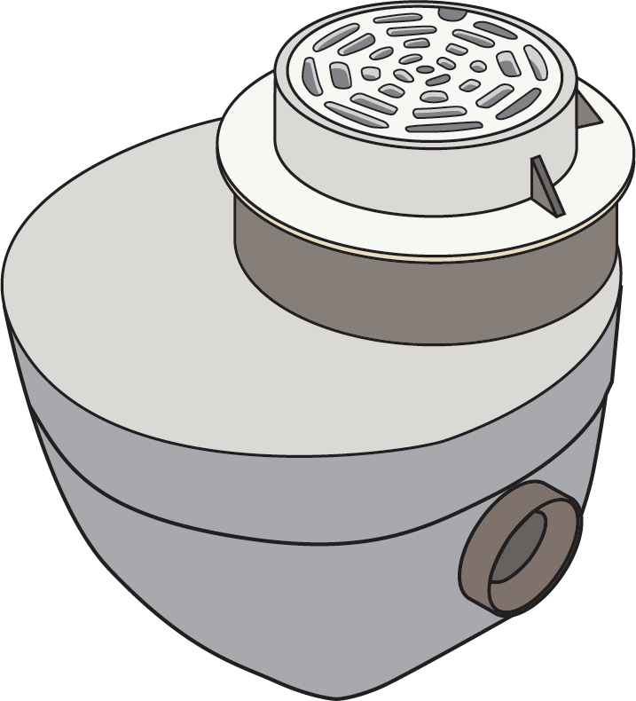
Catch basins are generally manufactured of concrete in round and rectangular configurations and in many different sizes to suit the application. Round catch basins (Figure 1) are designed to accept an eccentric concrete lid that may have one of various opening styles that suit the required casting. Grade or extension rings are used on top of the concrete lid to bring the drain grate assembly up vertically to match the grade of the surface being drained. Cylindrical catch basins are the more common variety used in the field.
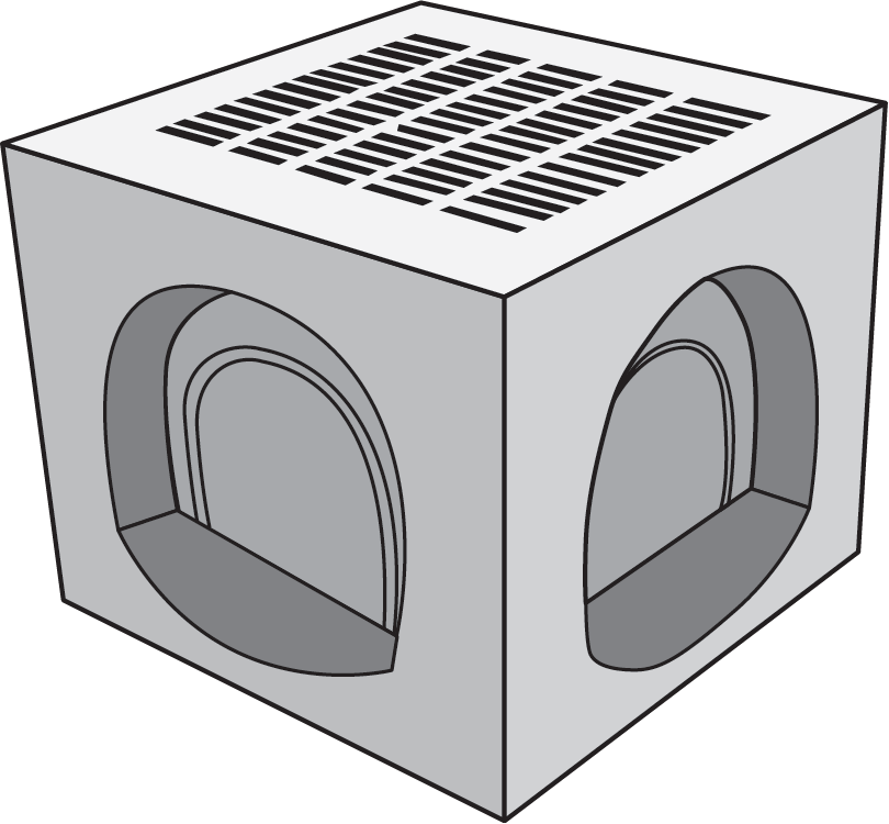
Rectangular catch basins are often designed to have the cast-iron frame and grate sit directly on top without needing a concrete lid (Figure 2).
Reinforcing steel bars (rebar) and wire mesh are cast into high compressive strength concrete to ensure that the catch basin can withstand the loads imposed on them without fracturing. The catch basins may be constructed with bottoms, or bottoms may be poured in place once the catch basin is located. Loops of rebar or wire rope are cast into the body so that they can be used as lifting eyes (attachment points) for placement using a crane or backhoe. Concrete basins may have pipe openings pre-cast into them; otherwise, the openings are cut into them after they have been set in place.
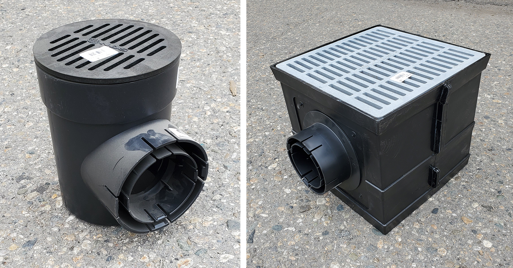
Smaller plastic catch basins, both round and square, (Figure 3), are available at most home improvement retail stores and plumbing wholesalers. They are of light duty construction and are widely used for residential landscaping in areas where there is no possibility of vehicular traffic on them.
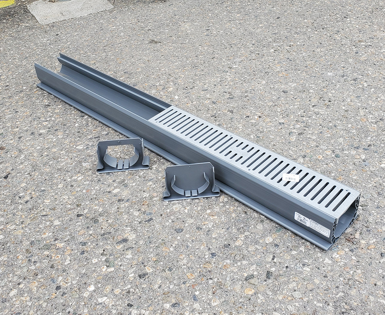
Drainage Troughs
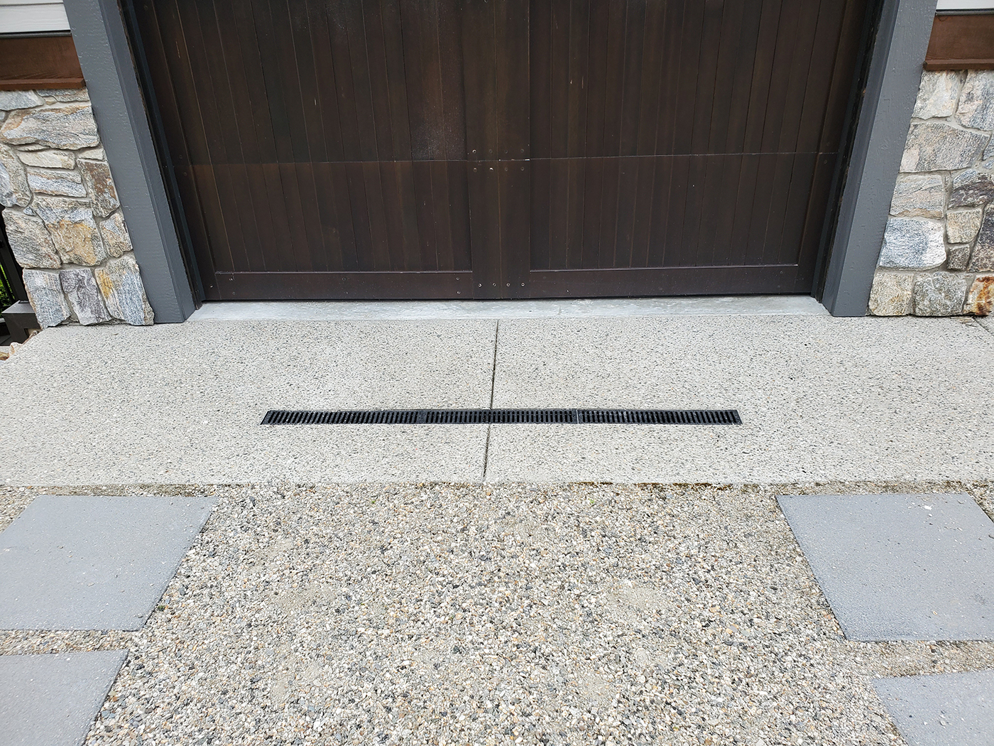
Drainage troughs are another form of catch basin (Figure 4). They can be as long as needed and are fairly narrow. They are usually installed across driveways that are lower in elevation at the end nearest the building than at the street. They are preferred where water must be intercepted as it flows across a wide plane of sloped pavement or concrete rather than through a round or rectangular grate that has the area surrounding it graded to its central location. Water that would otherwise flow down the driveway and into the building is instead directed into the trough drain and carried away to the storm drainage system.
Trough or trench drains, as they are sometimes called, are constructed of either poured-in-place concrete or high strength plastic and have a narrow removable grate at the top where the runoff water enters. They are typically very shallow, and because of their limited depth, there is no downturned 90° elbow. Instead, the horizontal pipe outlet is located an inch or two above the bottom of the trench body (Figure 5). This allows a small amount of vertical space below the outlet’s invert in which any sediment can be held back and accumulate. Accordingly, due to its limited sediment storage capacity, a trough or trench drain must be cleaned out more frequently than a catch basin.
Catch Basin Operation
A catch basin’s purpose is to allow surface runoff to drain while preventing sediment and debris from being carried out into the storm drainage system. This is accomplished by using a downturned 90° elbow and having some significant depth below it.
A cross-section of a typical heavy-duty concrete catch basin, such as what might be found in a parking lot, is shown in Figure 6. Notice that any sediment and debris carried through the drain grate with the runoff will settle and accumulate at the bottom of the basin. Once the depth of the sediment is sufficient, the drain grate is removed and the sediment can either be “mucked out” with hand tools or vacuumed out using a “jet vac” style of truck. Most catch basins are designed with at least a foot or more of liquid depth to allow sediment to accumulate while reducing the frequency of cleanings.
The liquid depth of a catch basin is measured between the bottom of the basin and the invert of the pipe leaving the basin. A key to trouble-free operation of catch basins is the use of a downturned 90° elbow with a short length of pipe extending into the liquid. This arrangement allows the water in the basin to drain while preventing anything that floats on the water’s surface from being carried into the pipe. Some catch basins have a manufactured version of the elbow cast-in-place so that the installer only needs to connect the pipe to the outlet.
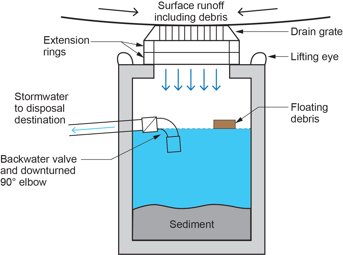
Catch basins may have a backwater valve installed downstream of the 90°. The intent of the backwater valve is to help prevent any surcharge (reverse flow) from coming back through the discharge piping into the catch basin and flooding the area. Backwater valves commonly have a rubber seal to allow them to close tight, but if the valve is not checked and maintained, it may not prevent reverse flow, and its installation may be ineffective.
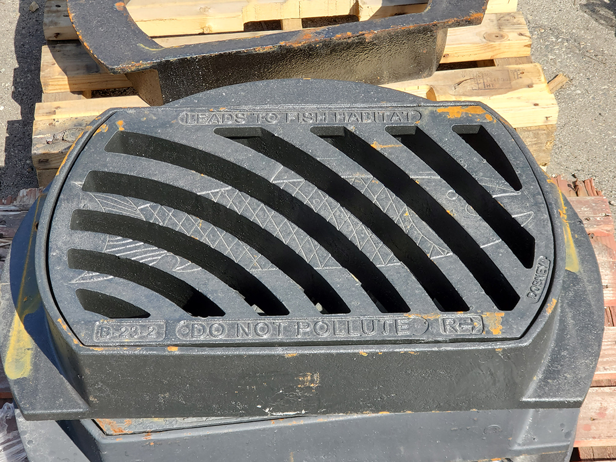
In areas with dedicated storm sewers, the water from catch basins is carried through underground pipes to local streams, ditches, and other acceptable places of disposal instead of being taken to the sewage treatment plant along with household and industrial wastewater, as it is in a combined system. If the eventual discharge destination is a fish-bearing body of water, most AHJs will inform the public of the sensitivity to that environment by painting an icon of a fish on the concrete or paved surface adjacent to it. Some manufacturers now cast environmental warnings into their drain grates, as seen in Figure 7. These endeavours are meant to dissuade the public from allowing contaminants to enter the system and affect the environment.
Installation
When installing a concrete catch basin, a hole is dug and the ground beneath its intended location is levelled and compacted. The basin is set into place and levelled. The drain grate is set to elevation using extension rings of varying thickness grouted to the basin’s top. The piping outlet elevation is determined and, if no pre-cast pipe opening has been provided, the wall of the concrete basin must be broken into using percussion tools and hammers. Any interior rebar or wire mesh is cut out of the way, the pipe is inserted into the new rough opening, and the penetration is sealed with grout.
Sumps
A sump differs from the definition of a catch basin in that a sump is usually a catch basin that cannot be drained by gravity because of its location and, therefore, needs to be pumped out. As well, sumps usually do not have an open drain grate on their top. They are sealed chambers with pipe inlets at either the top, sides, or both.
Sumps can be used for either stormwater or sanitary waste. An example of a storm sump would be one that is installed in the lowest level of an underground parkade in a large building. Discharge from all the floor drains for the parkade would be piped into the sump, and be pumped from there up into the storm building drain.
Using a sump for sewage is probably more common than for stormwater because there are many buildings where the lowest plumbing fixtures cannot drain by gravity if the building drain leaves the building at a higher elevation than that of the fixture drains. As well, sometimes a fixture, such as a clothes washer, needs to be located in an area where there is no roughed-in drainage piping. Rather than omit any fixtures in these situations, sewage sumps allow for fixture placement without possibly having to jackhammer into concrete floors. Fixtures drain by gravity into the sump, and sump pumps lift the sewage and discharge it into the sanitary building drain.
Regulations
Regardless of the contents of the sump (storm or sanitary), the National and BC Plumbing Codes address the installation of sumps in Article 2.4.6.3. Listed below are those code clauses.
2.4.6.3. Sumps or Tanks (See Note A-2.4.6.3.):
- Piping that is too low to drain into a building sewer by gravity shall be drained to a sump or receiving tank.
- Where the sump or tank receives sewage, it shall be water- and airtight and shall be vented.
- Equipment such as a pump or ejector that can lift the contents of the sump or tank and discharge it into the building drain or building sewer shall be installed.
- Where the equipment does not operate automatically, the capacity of the sump shall be sufficient to hold at least a 24-hour accumulation of liquid.
- Where there is a building trap, the discharge pipe from the equipment shall be connected to the building drain downstream of the trap.
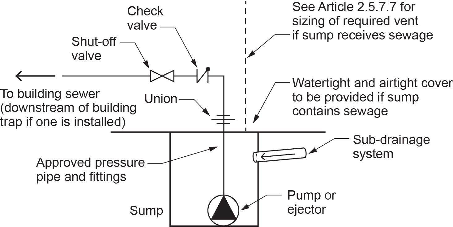
- The discharge pipe from every pumped sump shall be equipped with a union, a backwater valve and a shutoff valve installed in that sequence in the direction of discharge.
- The discharge piping from a pump or ejector shall be sized for optimum flow velocities at pump design conditions.
Note: A-2.4.6.3. from the codes shows a typical sump piping configuration, as replicated in Figure 8.
Note: The sump is receiving discharge from a “sub-drainage system.” Although no definition exists, a sub-drainage system is widely held to be any piping that carries liquid waste that is too low to drain by gravity to a building drain and, therefore, must be drained into a sump.
In large commercial settings, sumps are either cast-in-place (formed and poured in concrete) or constructed of large sections (rings) of pre-cast concrete. The rings are stacked one onto another, with the seams grouted to make them watertight. A level floor is poured and made ready for pumps to be installed on them. Pre-cast sumps are also an option if of a smaller size.
The pumps and related controls and piping are installed so that the system works automatically. There is provision in the codes for a sump to have it be pumped out as part of a building operator’s daily routine (see Subclause 4 above), but the sump would have to be sized to hold at least a 24-hour accumulation of liquid. This usually translates into a very large sump, and so the preference is for automatic control.
In large installations, the system is usually duplex, meaning that there are two pumps in the sump, each with its own union, check valve, and shutoff and piped in parallel. A series of float switches on electrical cord are suspended inside the sump. They are wired to a control panel that operates the pumps.
Sump Operation
Figure 9 shows four float switches, all at different levels, controlling two pumps. As the liquid level rises in the sump, the lowest switch starts to tip upward. A heavy lead weight is attached to the electrical cord just above each float to ensure that the float will be inverted vertically when the liquid level rises above it. At this point, the lowest float switch (#1) being inverted will not cause anything to occur.
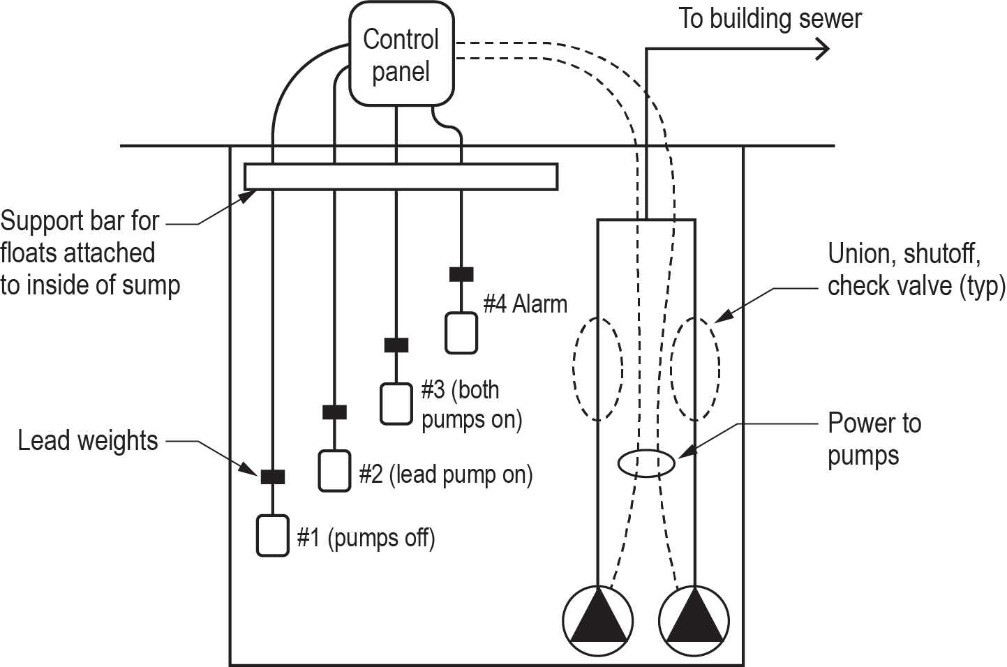
As the liquid level rises, float switch #2 tips upward. When the float is almost fully inverted, a switch inside it “makes” or closes, which sends a signal to the control panel. The control panel sends power to one of the two pumps, which turns on and starts to pump the liquid out through the piping to the building sewer. As the liquid level drops, float switch #2 hangs vertically again, but the pump continues to run. The pump will continue to operate until float switch #1 hangs vertically, at which point the switch contacts inside it “break” or open, and the pump shuts off.
Through normal operation, as the liquid level in the sump rises and falls, the control panel will operate the same pump on and off, while the other pump is on standby as a backup. This is known as “lead-lag” control. If desired, micro-switches inside the control panel can be configured so that the pumps take turns with normal operation. This is known as “alternating control.”
Float switches #3 and #4 come into play in situations where, due to excessive inflow or possibly a pump that has malfunctioned, the liquid level continues to rise. If float switch #3 inverts, the control panel will power both pumps. In that way, if the lead pump has malfunctioned during normal inflows, the lag pump should be able to handle the flow and pump down the sump. If the lead pump cannot handle the excessive inflow, then both pumps should be able to pump down the sump. This is assuming, of course, that the pumps have been sized correctly.
If the liquid level gets to the point where float switch #4 is inverted, the control panel will sound a local alarm and possibly remote alarms as well.
Rather than have a horizontal support bar with a lead weight above each float, another option for installing the floats is to fix a small-diameter vertical pipe — made of galvanized iron, copper, or some other corrosion-resistant material — inside the sump (Figure 10). The cords of the float switches are taped or “zap-strapped” to the pipe a few inches above each float and one above the other. This negates the use of the lead weights while still allowing the float to tip upside down.
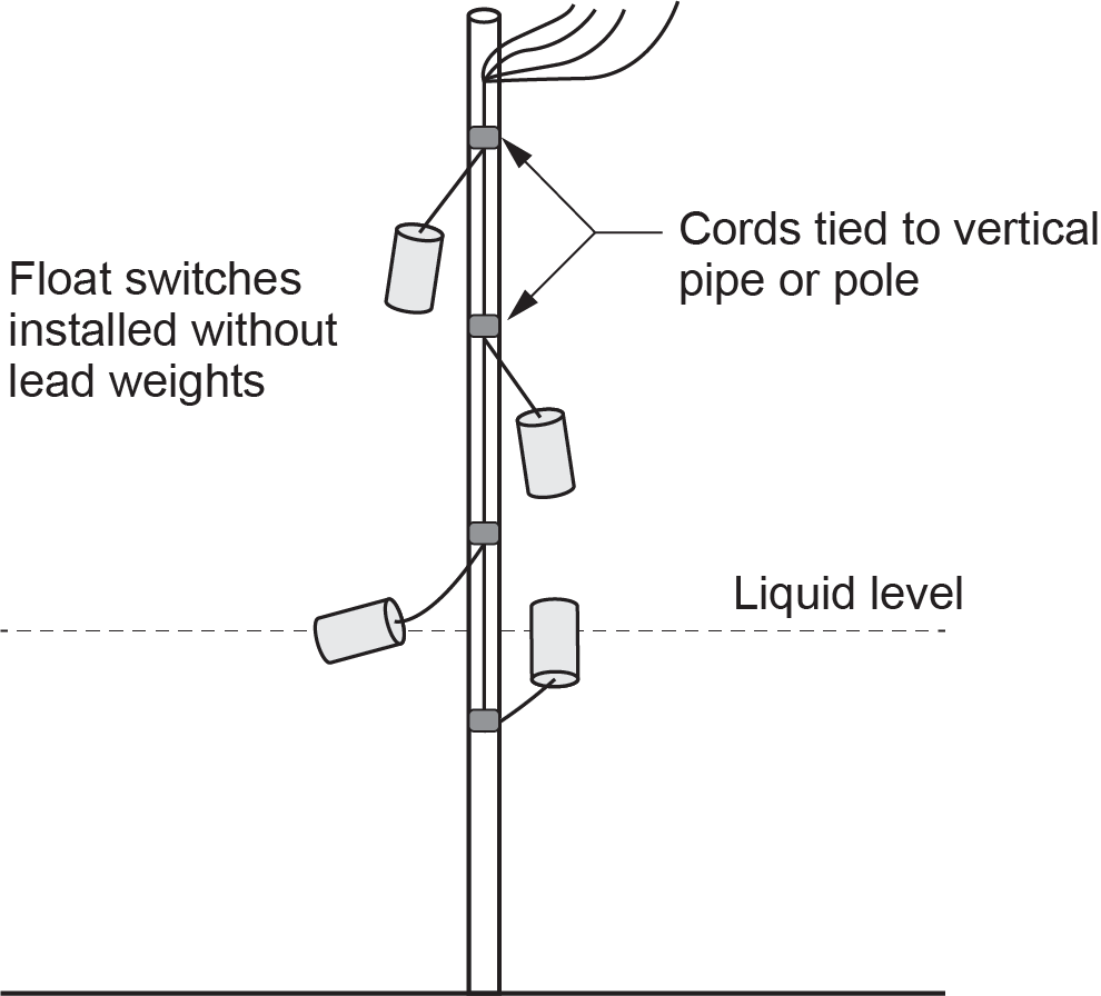
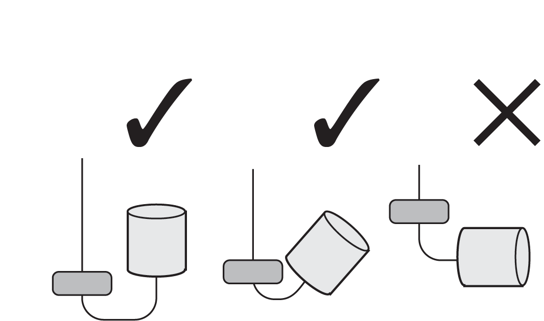
Cylindrical float switches will not “make” if the float does not invert. Without either a lead weight or the cord being tied off, the float switch will float in a horizontal orientation and will not engage the switch (Figure 11).
Sump Pump Installation
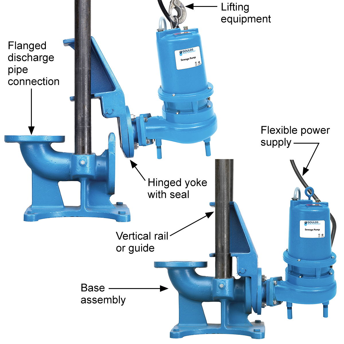
Small sump pumps, with outlet diameters two inches or less, are relatively easy to set into and pull from a sump. Cast-iron pumps three inches and larger are very heavy, and so there are support systems on guides and rails available to make installation, operation, and removal much easier.
Figure 12 shows a pump that only has to be winched in and out of the sump using lifting equipment. There are no electrical or piping connections in the bottom of the sump that need to be accessed to allow the pump to either be placed or removed. A cast-iron base with one or two vertical rails is bolted to the floor of the sump, and the rails are bolted to the inside of the sump near its top. The pump is mounted on a yoke that slides down the vertical rails to where it rests against the base. A hinged pipe connection, using rubber rings for sealing the yoke to the base, and flexible power supplies allow the pumps to be set in place or lifted out of the sump where they can more easily be worked on. Pumps used in large commercial installations are commonly high-voltage three-phase models.
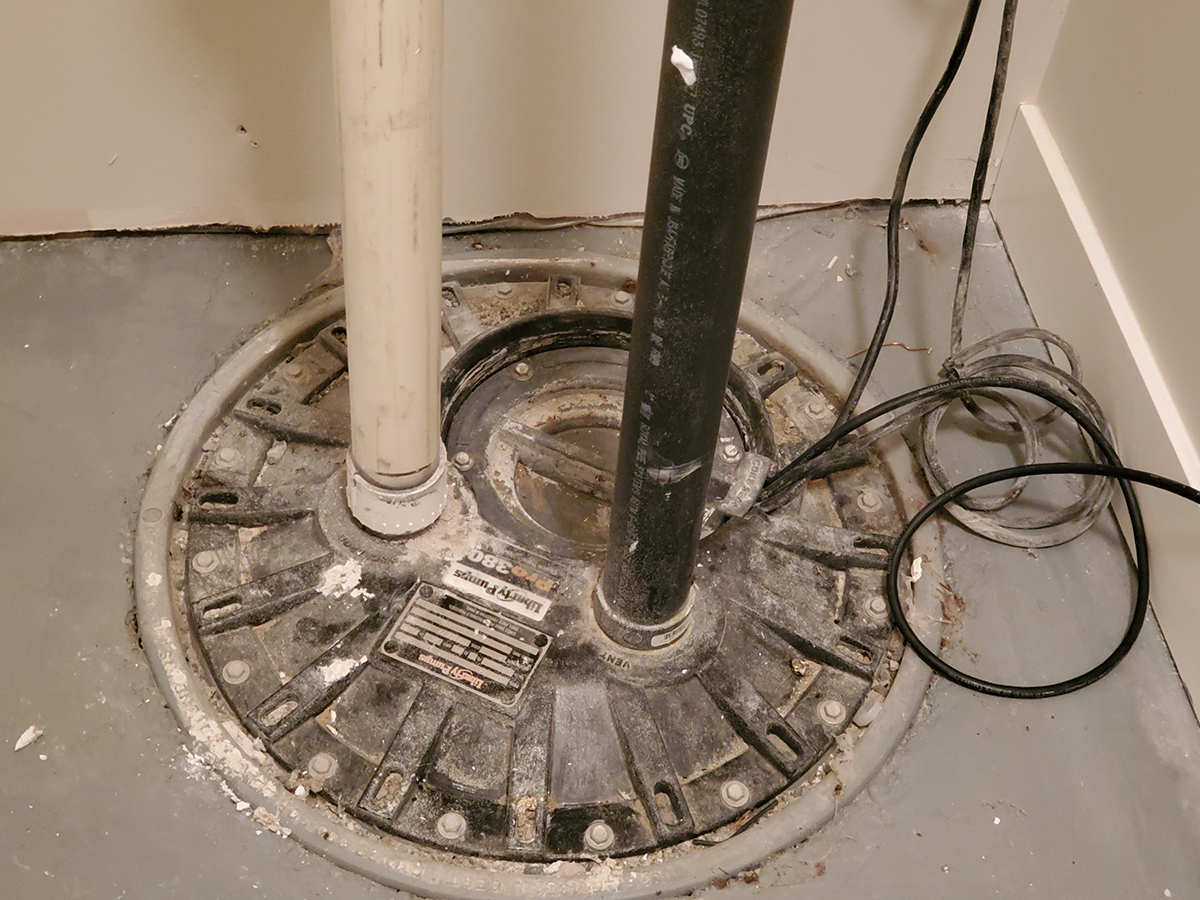
Small packaged sump kits are commonly used in residential settings for basement bathrooms and laundries where the building drain is installed above the basement floor. A plastic tank with a sealed lid is furnished with a single submersible pump that is operated with a single float switch (Figure 13). The float switch is duplex in that it turns the pump on when inverted and off when back to its normal “hanging” position. There is a single inlet into the side of the tank, and the lid has openings for the discharge pipe, a vent, and a power cord.
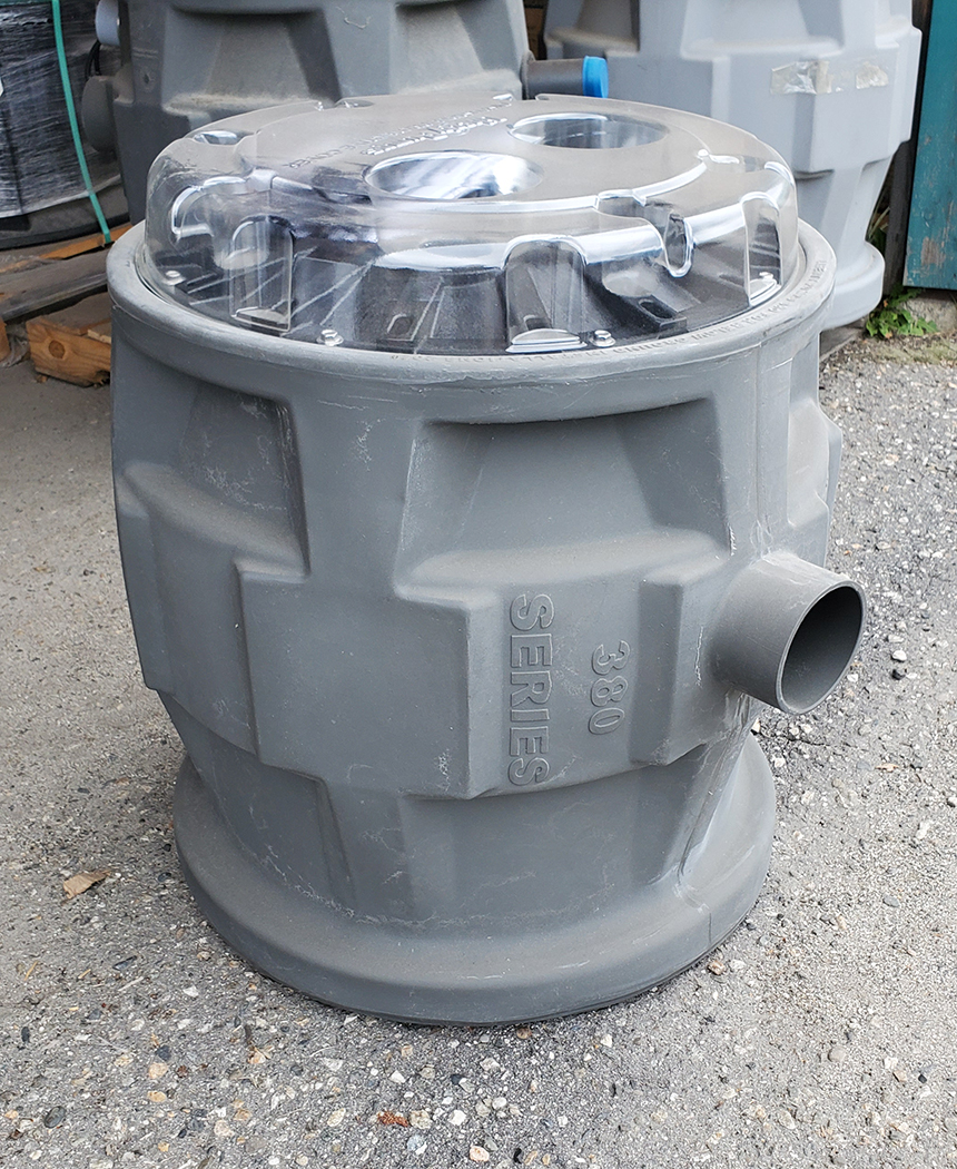
The lid and all the openings have rubber seals to make the sump package water- and airtight. If the drainage piping is below floor elevation, the sump can be recessed and embedded (Figure 14).
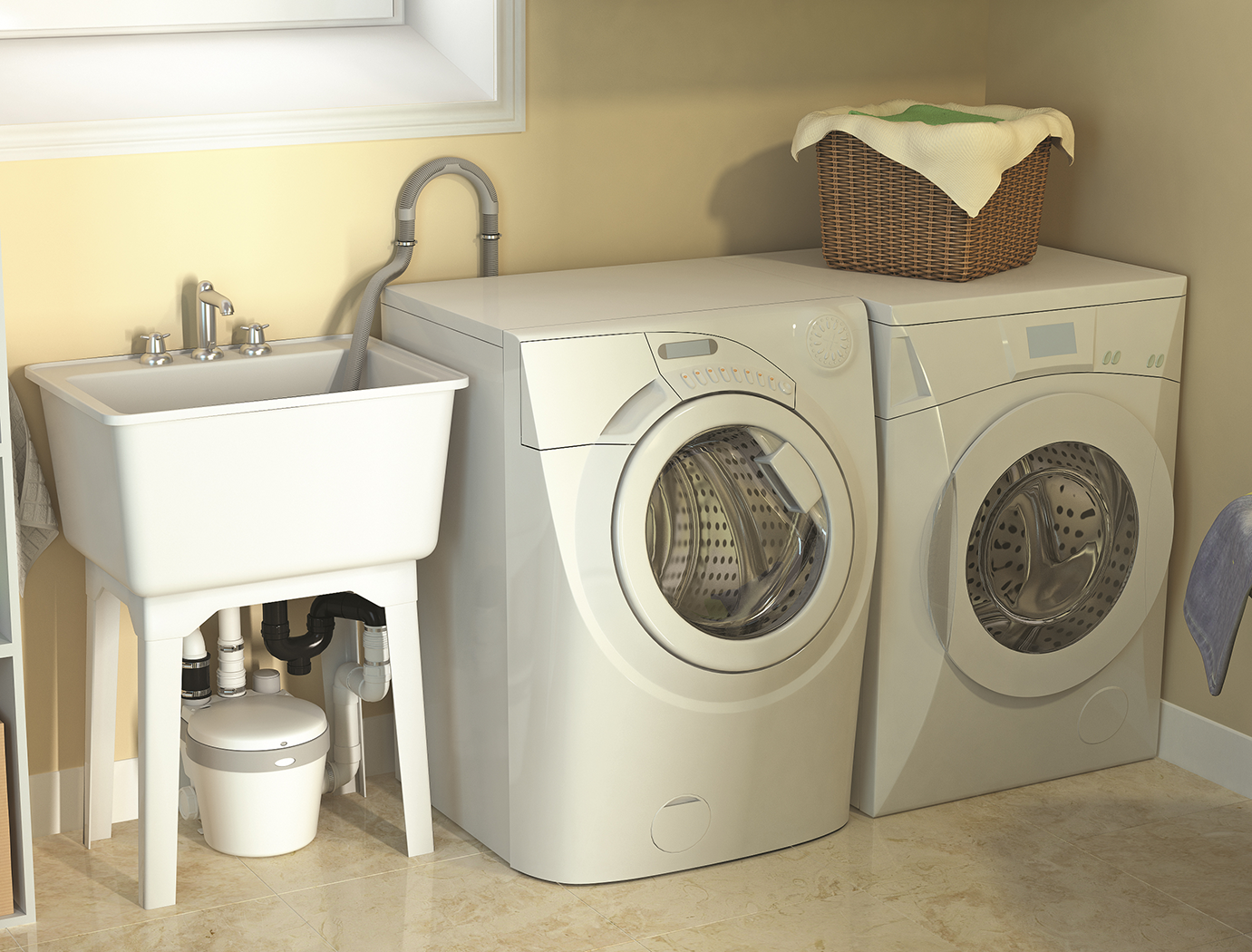
If the fixture to be drained does not need to have buried piping, then an above-ground model of sump kit can be installed. In a laundry room, the clothes washer and laundry tub are drained through piping located above grade, so a plastic packaged sump can be installed on the floor near the fixtures. It will have either a side or top inlet, or sometimes both. Just like the recessed models, the removable lid will have openings with rubber seals for the discharge pipe, vent, and power cord (Figure 15).
Due to their limitations for placement, most above-ground sump kits have a capacity of only a few gallons, while below-ground models can be as large as desired. A common size for below-ground sump basins is 18 in. diameter by 32 in. deep, which would have a capacity of approximately 30 imp gal. Their pumps would have longer standby and run times than their smaller above-ground counterparts and should, therefore, have a longer life.
Any equipment that starts and stops frequently is more prone to wearing out and requiring service than that which operates less frequently and for a longer period. Access to above-ground sump pumps is normally easier than for below-ground units.
Some models of toilets are manufactured to be both a fixture and a sump (Figure 14). Known as “macerating toilets,” they are rear-discharge to a sump that also has openings on either side to accept drainage pipes from bathtubs, showers, and basins. The upside to these styles of toilets is that they and the accompanying fixtures can be installed in basements without the need to break up concrete flooring.
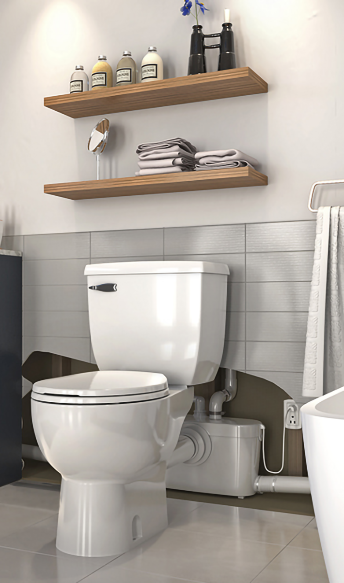
The downside is that the drainage from the other fixtures is also above grade and may need to be exposed. As well, bathtubs and showers usually need to be installed on raised platforms in order to get their drainage piping high enough to connect to the macerating toilet’s sump inlets. If aesthetics is a major consideration, then the installation of a below-ground sump is the better choice.
The electrical power needed for most above or below grade sump pumps is of the common household variety, which is single-phase, 120-volt alternating current supplied through a standard three-prong plug receptacle.
 Self Test D-3.6: Sumps and Catch Basins
Complete Self Test D-3.6 and check your answers.
If you are using a printed copy, please find Self-Test D-3.6 and Answer Key at the end of this section. If you prefer, you can scan the QR code with your digital device to go directly to the interactive Self-Test.

References
Saniflo. (2021, May). Four affordable, value-adding home improvements real estate agents suggest! Blog 05/01/2021[Image]. Used with permission. Retrieved from https://www.saniflo.ca/us/blog/-four-affordable-value-adding-home-improvements-real-estate-agents-suggest-n292
Saniflo. (n.d.). Saniaccess 3: Installing an additional bathroom [Webpage]. Retrieved from https://www.sfasaniflo.com/us/installing-an-additional-bathroom/68-saniaccess-3.html
Skilled Trades BC. (2021). Book 2: Install fixtures and appliances, install sanitary and storm drainage systems. Plumber apprenticeship program level 2 book 2 (Harmonized). Crown Publications: King’s Printer for British Columbia.
Trades Training BC. (2021). D-3: Install storm drainage systems. In: Plumber Apprenticeship Program: Level 2. Industry Training Authority, BC.
Xylem Inc. (n.d.). Guide rails – 3” & 4”. Xylem. https://www.xylem.com/en-us/products–services/pumps-packaged-pump-systems/pumping-accessories/goulds-water-technology-accessories/guide-rails-3-and-4/
Media Attributions
All figures are used with permission from Skilled Trades BC (2021) unless otherwise noted.
- Figure 12: Large-diameter sump pump installation on rails from Xylem Inc. (n.d.) was adapted by Skilled Trades BC (2021) and used with permission from Xylem Canada, LLP.
- Figure 15: Above-grade sump kit for laundry fixtures from Saniflo was adapted by Skilled Trades BC (2021) and used with permission.
- Figure 16: Above grade from Saniflo was adapted by Skilled Trades BC (2021) and is used with permission.
A pit or tank used to collect waste water that can't flow by itself into the sewer. (Section D-1.10)
A ground-level stormwater collection point, often found in paved areas, that traps debris like leaves before directing rainwater or stormwater into pipes for proper drainage. It has a grate on top to catch debris and prevent blockages, helping direct the water into storm sewers for discharge into natural water bodies. (Section D-3.2; Section D-3.6)
A receptacle installed to prevent unwanted materials from passing into a drainage system. There are three main types of interceptors: grease, oil, and solids. Each of them requires different considerations for sizing, operation, and maintenance. (Figure 20, Section D-1.2; Section D-1.11)
Any solid, liquid, or gas that may impair the quality of the potable water. (Section D-3.3)
Water that is found on the surface of the Earth, like in rivers, lakes, ponds, or oceans. It comes from rainfall, melting snow, or water flowing from other places. (Section D-3.6)
A narrow channel or trench that collects and moves water away from areas like driveways or parking lots. Made of concrete or plastic, it has a grate on top for water to flow into, helping keep the area dry and safe. (Figure 4, Section D-3.6)
A network of pipes or drains placed underground to collect and carry away excess water from the soil. It helps prevent flooding or water buildup by directing water to safe areas, keeping the ground dry and stable. (Section D-3.6)
Two pumps in a sump, each with its own pipes and valves. Float switches inside the sump detect water levels, and a control panel automatically turns the pumps on or off. This setup ensures the system works even if one pump fails. (Section D-3.6)
A device that controls water levels in tanks or pumps. It has a floating part that moves with the water level, and when the water gets too high or low, it sends a signal to turn the pump on or off to keep the water at the right level. (Section D-3.6)
