D-3.3 Storm Drainage Code Requirements
The National Plumbing Code (NPC) has established a minimum acceptable standard for the design and installation of storm and combined drainage systems. Because sanitary drainage systems were studied in Section E-1 of this series, this chapter will only focus on the sections of the NPC that deal with storm and combined drainage systems.
Piping Types
Piping materials used to construct an interior storm drainage system must be acceptable to the AHJ and the Code. Exposed leaders or downspouts should be capable of withstanding all anticipated abuses, corrosion, weather, and expected expansion and contraction. The piping may be the same material approved for sanitary drainage whether it is installed in any of the following ways:
- Above ground inside the building
- Underground under the building
- As a building sewer
The following are exceptions to the piping material approved for sanitary drainage.
Corrugated Steel Galvanized Pipe
Corrugated steel galvanized pipe is typically used in a variety of applications, such as culverts, stormwater detention systems, and storm sewers. Couplings for corrugated steel pipe shall be constructed so that, when installed, they:
- Maintain the pipe alignment
- Resist the separation of adjoining lengths of pipe
- Prevent root penetration
- Prevent the infiltration of surrounding material
Application
| Drainage System | Venting System | |||
|---|---|---|---|---|
| Above Ground Inside Building | Underground Under Building | Building Sewer | Above Ground | Underground |
| N | N | P (only as a storm sewer) | N | N |
Sheet Metal Leaders
A sheet metal leader shall not be used except above ground outside a building.
Piping Identification
The NPC requires that every length of pipe and every fitting have cast, stamped, or indelibly marked on it the maker’s name or mark as well as the weight, class, or quality of the product. It must also be marked in accordance with the relevant standard. These pipe markings must be visible after installation.
Size
Rainwater leaders, storm and combined building drains, and storm and combined building sewers are all part of the storm drainage system. To size the above-mentioned piping sections, you must understand that the load to consider is measured in litres (L). For the load of litres to have any relationship to flow rate, there must be a time frame associated with it. The time frame used is a 15-minute rain event. Even though the load on a pipe is expressed in litres, it really means it is litres per 15 minutes (L/15 min).
This 15-minute time frame is associated with climatic data listed in the National Building Code. This document lists different geographical locations and their local rainfall intensity. The rainfall intensity is the depth of water, in millimetres, received during a rain event over a 15 minute period, expressed as mm/15 min.
Determining the Drainage Load for a Flat Surface
To calculate the load in litres per 15 minutes from a roof or paved surface, we must know the area being drained. The area will be expressed in square metres (m2). The question is, how do the area of a roof and the rainfall intensity relate to a load in litres per 15 minutes?
Figure 1 shows a roof surface with a roof drain in the centre. The area of the surface being served by the roof drain is 1 m2.
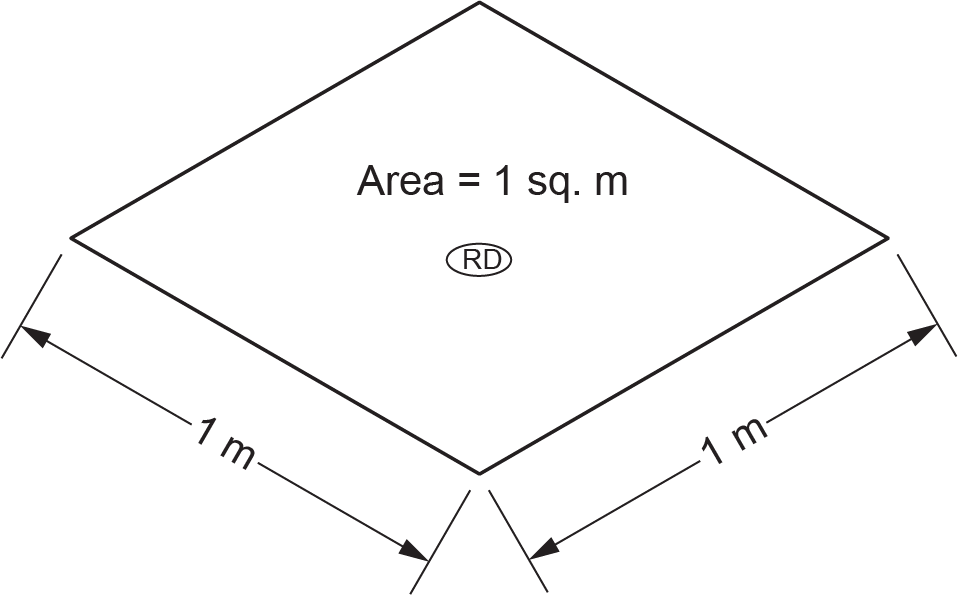
If the surface had a water depth of one mm, the resulting volume would be one litre. Why is that? Well, we must know that:
- The area measurement, one square metre (m2), contains one million mm2:
[latex]\color{blue}{1000\text{ mm}\times1000\text{ mm}=1000000\text{ mm}^2}[/latex]
- The volumetric measurement, one litre, contains one million mm3 of volume:
[latex]\color{blue}{1000\text{ mm}\times1000\text{ mm}\times1\text{ mm}=1000000\text{ mm}^3}[/latex]
If the depth were 2 mm, then the volume of water on the surface would be 2 L, and so on. If this roof were located in Burnaby, BC, which has a rainfall intensity of 10 mm/15 min, then it could be deduced that the 1 m2 surface area and the associated roof drain would receive 10 L of flow in 15 minutes.
To find the load for any drained surface expressed in litres per 15 minutes, simply multiply the area in m2 by the rainfall intensity in millimetres per 15 minutes.
Example
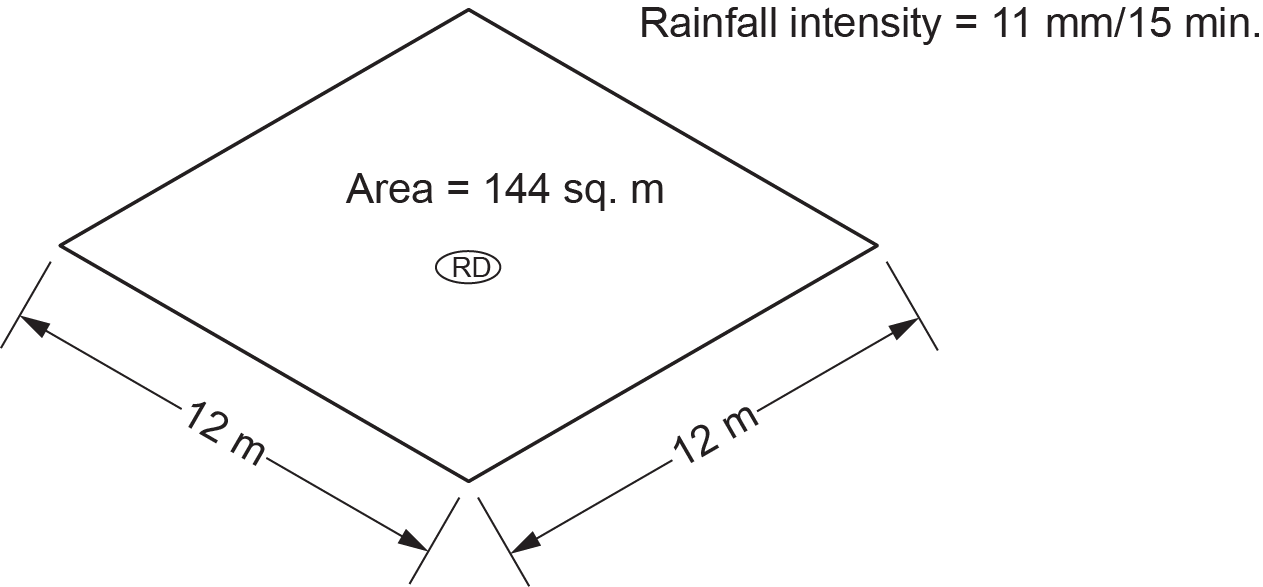
Figure 2 shows a [latex]12 \text{ m}\times12\text{ m}[/latex] roof
Solution
- Calculate the area of the roof surface:
[latex]\color{blue}{12 \text{ m}\times12\text{ m}=144\text{ m}^2}[/latex]
- Find the rainfall intensity given on the drawing:
[latex]\color{blue}{11\text{ mm}/15\text{ min}}[/latex]
- Determine the load on the roof drain:
[latex]\color{blue}{144\text{ m}^2\times11\text{ mm/}15\text{ min}=1584\text{ L}}[/latex]
Determining the Drainage Load for a Flat Surface With an Adjoining Wall
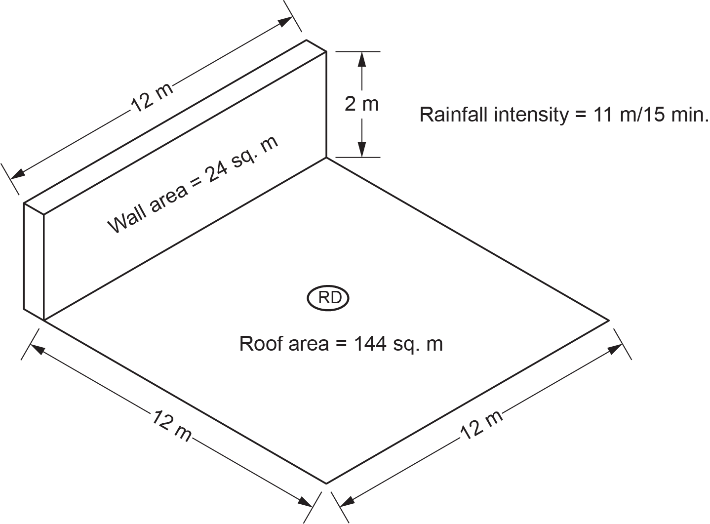
When determining the hydraulic load on the storm system from a roof with an adjoining wall, the calculation for the flat surface is the same as above (roof area x rainfall intensity). The NPC requires that the area of the wall be considered as well but not the whole wall; only one-half of the wall area must be considered when determining the effective area served by the roof drain.
Example
In Figure 3, a vertical adjoining wall has been added to our previous example. What is the load served by the roof drain?
Solution
- Calculate the area of the roof surface:
[latex]\color{blue}{12\text{ m}\times12\text{ m}=144\text{ m}^2}[/latex]
- Calculate the area of the wall surface and divide by 2 (one-half):
[latex]\color{blue}{12 \text{ m}\times2\text{ m}=24\text{ m}^2\div2=12\text{ m}^2}[/latex]
- Calculate the total effective area served by the roof drain:
[latex]\color{blue}{144\text{ m}^2\text{ (roof)}+12\text{ m}^2\text{ (wall)}=156\text{ m}^2}[/latex]
- Find the rainfall intensity given on the drawing:
[latex]\color{blue}{11\text{ mm}/15\text{ min}}[/latex]
- Determine the load on the roof drain:
[latex]\color{blue}{156\text{ m}^2\times11\text{ mm}/15\text{ min}=1716\text{ L}}[/latex]
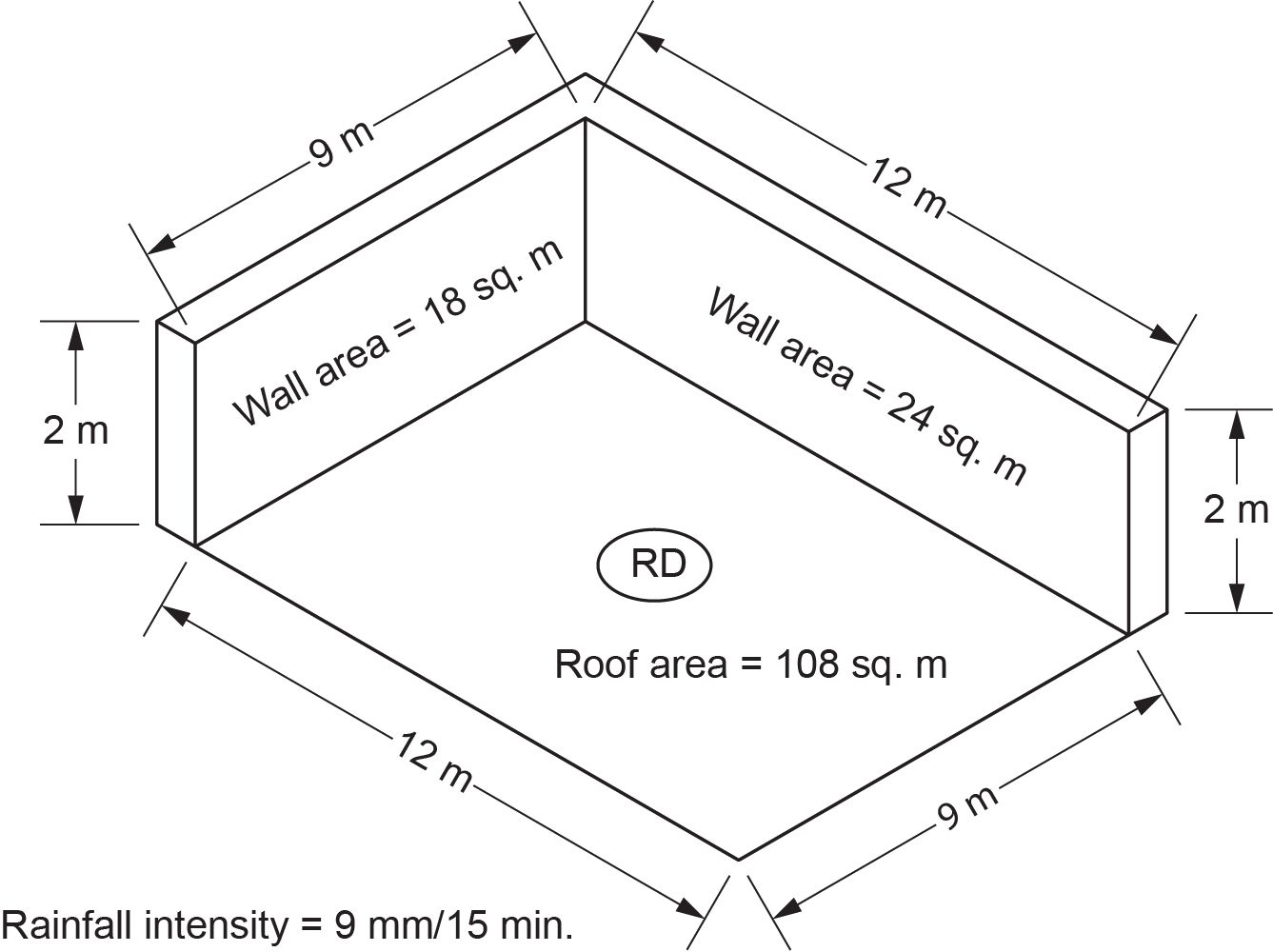
When determining the hydraulic load to the storm system from a roof with two or more adjoining walls, the NPC requires that only one-half of the largest adjoining wall area be considered.
Example
In Figure 4, a roof drain serves a flat roof surface and two vertical adjoining walls. Only half the area of the largest wall will be considered in our calculations, as the other wall will be ignored. The location of the installation has a rainfall intensity of 9 mm/15 min. What is the load served by the roof drain?
Solution
- Calculate the area of the roof surface:
[latex]\color{blue}{9\text{ m}\times12\text{ m}=108\text{ m}^2}[/latex]
- Calculate the area of the largest wall surface and divide by 2 (one-half):
[latex]\color{blue}{12\text{ m}\times2\text{ m}=24\text{ m}^2\div 2=12\text{ m}^2}[/latex]
- Calculate the total effective area served by the roof drain:
[latex]\color{blue}{108\text{ m}^2\text{ (roof)}+12\text{ m}^2\text{ (wall)} = 120\text{ m}^2}[/latex]
- Find the rainfall intensity given on the drawing:
[latex]\color{blue}{9\text{ mm}/15\text{ min}}[/latex]
- Determine the load on the roof drain:
[latex]\color{blue}{120\text{ m}^2\times9\text{ mm}/15\text{ min}= 1080\text{ L}}[/latex]
Determining the Load From an Appliance That Produces Semi-continuous or Continuous Flow
Fixtures and appliances that discharge semi-continuous or continuous flow are allowed to drain to either sanitary or storm drainage systems. The one stipulation is that only fixtures or appliances that discharge clearwater waste may drain to a storm drainage system. Recall from Section D-1 that when a fixture with semi-continuous or continuous flow drains to a sanitary drainage system, the flow rate from that fixture is expressed in litres per second is multiplied by 31.7 to find the hydraulic load, expressed in fixture units (FUs), imposed on the sanitary system by that fixture. Also, the size of the trap serving that flow was sized from Table 2.4.10.12. based on the flow rate, in litres per second, from that fixture. The reason we had to convert between a flow rate in litres per second to fixture units is that all sanitary drainage piping uses fixture units as the measurement for hydraulic load.
In storm and combined drainage systems, the unit of measure for hydraulic load is litres per 15 minutes. Because of this, when connecting a semi-continuous or continuous flow appliance with a flow rate expressed in litres per second to a storm or combined drainage system, another conversion must be used. To accomplish this, as stated in Clause 2.4.10.3.(2), simply multiply the flow rate (L/s) by 900 (number of seconds in 15 minutes) to get a hydraulic load in the proper format (L/15 min) for sizing the storm or combined system.
Example
What would be the hydraulic load imposed on a storm or combined drainage system when the flow rate from the fixture or appliance is 0.35 L/s?
Solution
Convert the flow rate in L/s to L/15 min:
[latex]\color{blue}{0.35\text{ L}/\text{ s}\times900\text{ s}/15\text{ min}=\text{ L}/15\text{ min}\;0.35\times900 = 315\text{ L}/15\text{ min}}[/latex]
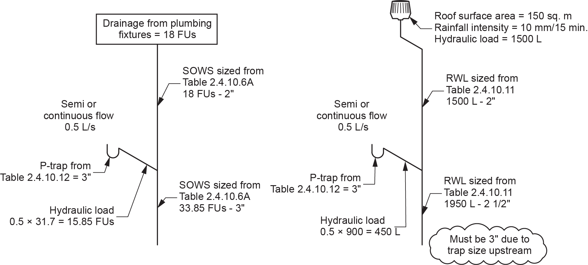
Figure 5 compares the hydraulic loads when connecting an identical appliance to both a SOWS and an RWL. Pay special attention to the size of the RWL downstream of the appliance connection and why its size must be larger than required by the code tables.
NPC Sizing Tables
Sizing pipe for a storm or combined drainage system is a relatively straightforward process once you are familiar with the tables provided in the NPC book. These tables provide the minimum size of all drainage pipes based on the load, in litres, it can carry for any particular size. Remember that the load on any pipe section is the load draining to it from upstream.
Because there are different tables for sizing leaders, gutters, and building drains/sewers, you must be able to properly identify the proper table for the pipe section you are sizing.
The following tables are the ones you will need to refer to.
Table 2.4.10.9. — Maximum Permitted Hydraulic Load Drained to a Storm Building Drain or Sewer or a Combined Building Sewer
The storm or combined building drain conducts flow from the furthest point upstream and terminates 1 m outside the foundation. At this point, the storm or combined building sewer is established and conducts the flow to an approved disposal system. To determine the size of any portion of the storm or combined building drain or the storm or combined building sewer, you must know the drainage load in litres (L) and the pipe grade. Notice that for any pipe size, the load-carrying capacity of the pipe increases as the grade is increased.
| Size of Drain or Sewer (in.) | Maximum Hydraulic Load (L) | ||||||
|---|---|---|---|---|---|---|---|
| Slope | |||||||
| 1 in 400 | 1 in 200 | 1 in 133 | 1 in 100 | 1 in 68 | in 50 | 1 in 25 | |
| 3 | N/A | N/A | N/A | N/A | N/A | 2,770 | 3,910 |
| 4 | N/A | N/A | N/A | 4,220 | 5,160 | 5,970 | 8,430 |
| 5 | N/A | N/A | 6,760 | 7,650 | 9,350 | 10,800 | 15,300 |
| 6 | N/A | N/A | 10,700 | 12,400 | 15,200 | 17,600 | 24,900 |
| 8 | N/A | 18,900 | 23,200 | 26,700 | 32,800 | 37,800 | 53,600 |
| 10 | N/A | 34,300 | 41,900 | 48,500 | 59,400 | 68,600 | 97,000 |
| 12 | 37,400 | 55,900 | 68,300 | 78,700 | 96,500 | 112,000 | 158,000 |
| 15 | 71,400 | 101,000 | 143,000 | 143,000 | 175,000 | 202,000 | 287,000 |
Table 2.4.10.10. — Maximum Permitted Hydraulic Load Drained to a Roof Gutter
To use this table, you need the load on the sloped roof as determined by its effective area and local rainfall intensity. Once the load has been determined, the slope of the gutter, in the direction of flow, becomes a determining factor. Once the slope ratio has been determined, the size of the gutter can be found in the column on the right side of the table. Gutter sizing and installation are not normally performed by plumbers. Gutter installation companies take care of gutters and external leaders.
| Size of Gutter (in.) | Area of Gutter (cm2) | Maximum Hydraulic Load (L) | |||
|---|---|---|---|---|---|
| Slope | |||||
| 1 in 200 | 1 in 100 | 1 in 50 | 1 in 25 | ||
| 3 | 22.8 | 406 | 559 | 812 | 1,140 |
| 4 | 40.5 | 838 | 1,190 | 1,700 | 2,410 |
| 5 | 63.3 | 1,470 | 2,080 | 2,950 | 4,170 |
| 6 | 91.2 | 2,260 | 3,200 | 4,520 | 6,530 |
| 7 | 124.1 | 3,250 | 4,600 | 6,500 | 9,190 |
| 8 | 162.1 | 4,700 | 6,600 | 9,400 | 13,200 |
| 10 | 253.4 | 8,480 | 12,000 | 17,000 | 23,600 |
Table 2.4.10.11. — Maximum Permitted Hydraulic Load Drained to a Leader
To use this table, you need to calculate the load on the leader, as determined by the effective area drained and local rainfall intensity. Once the load has been determined, you have a leader material choice between circular (pipe) and non-circular (downspout). Now, follow the appropriate column down to the calculated load’s range to determine the leader’s size.
| Circular Leader | Non-Circular Leader | ||
|---|---|---|---|
| Size of Leader (in.) | Maximum Hydraulic Load (L) | Area of Leader (cm2) | Maximum Hydraulic Load (L) |
| 2.5 | 3,070 | 31.6 | 2,770 |
| 3 | 5,000 | 45.6 | 4,500 |
| 4 | 10,800 | 81.1 | 9,700 |
| 5 | 19,500 | 126.6 | 17,600 |
| 6 | 31,800 | 182.4 | 28,700 |
| 8 | 68,300 | 324.3 | 61,500 |
Table 2.4.10.12. — Maximum Permitted Hydraulic Load From Fixtures With a Semi-continuous Flow
Sometimes, we need to size a trap serving a clearwater-waste–producing appliance that drains to a leader. When the flow is continuous or semi-continuous and expressed in litres per second (L/s), we can use that flow rate to find the minimum trap size in this table.
| Trap Size (in.) | Flow Rate (L/s) | Hydraulic Load (FUs) |
|---|---|---|
| 1.5 | 0.00–0.090 | 3 |
| 2 | 0.091–0.190 | 6 |
| 3 | 0.191–0.850 | 27 |
| 4 | 0.851–5.700 | 180 |
Sizing Procedures
When sizing storm and combined drainage systems, there are three different hydraulic load that could contribute to the process:
- Sanitary drainage from plumbing fixtures, expressed in FUs
- Storm drainage from roofs and paved surfaces, expressed in litres per 15 minutes
- Combined storm and sanitary drainage, expressed in litres per 15 minutes
The sizing process is best described by examining the hydraulic load contributors individually.
Sizing Sanitary Drainage
This process was described in detail in Section E-1, so we will not dwell on this subject. It is important to note that the hydraulic load generated by the sanitary system will become important later when we size the combined drainage system.
Sizing Storm Drainage
This process is relatively straightforward once the hydraulic load has been determined. The steps to follow are:
- Determine the effective area in m2 of roofs and paved surfaces.
- Determine the local rainfall intensity (millimetres per 15 minutes of rainfall) found in the National Building Code.
- Multiply the effective area by the rainfall intensity to obtain the hydraulic load in litres per 15 minutes.
Additional loads that may be considered when sizing a storm drainage system include:
- If a clearwater waste appliance or fixture discharges a continuous or semi-continuous flow to the storm system, multiply its load in litres per second by 900 to obtain the hydraulic load in litres per 15 minutes.
- If using flow-control roof drains, compute the discharge rate based on rain intensity, retention duration, accumulation height, and roof area from the roof drain manufacturer’s data.
Add all contributing hydraulic loads listed above to obtain the total hydraulic load on the storm drainage pipe in litres per 15 minutes. Then, consult the appropriate table from among Tables 2.4.10.9., 2.4.10.10., and 2.4.10.11. to select the drain, leader, or gutter size.
Storm Drainage Sizing Example
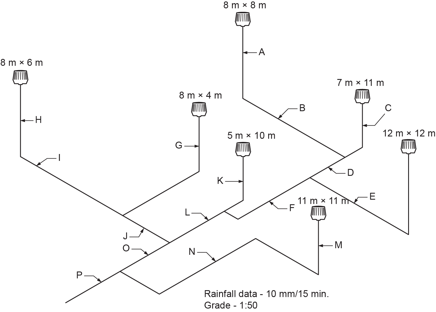
You can refer to Figure 6 to see the hydraulic load calculations in Table 6 illustrated on a map of a storm drainage system. Because there is no such thing as storm branches, all horizontal storm drainage pipes will be sized as storm building drains using the given grade ratio.
| Label | Name | Leader (m2) | Load (L) | Size |
|---|---|---|---|---|
| A | RWL | 64 | 640 | 2 in. |
| B | Storm building drain | − | 640 | 3 in. |
| C | RWL | 77 | 770 | 2 in. |
| D | Storm building drain | − | 1,410 | 3 in. |
| E | Storm building drain | − | 1,440 | 3 ft |
| F | Storm building drain | − | 2,850 | 4 in. |
| G | RWL | 32 | 320 | 2 in. |
| H | RWL | 48 | 480 | 2 in. |
| I | Storm building drain | − | 480 | 3 in. |
| J | – | − | 800 | 3 in. |
| K | RWL | 50 | 500 | 2 in. |
| L | Storm building drain | − | 3,350 | 4 in. |
| M | RWL | 121 | 1,210 | 2 in. |
| N | Storm building drain | − | 1,210 | 3 in. |
| O | Storm building drain | − | 4,150 | 4 in. |
| P | Storm building drain | − | 5,360 | 4 in. |
Sizing Combined Drainage
This process is more complex than the procedures we used in the above explanations. When sanitary drainage is connected to a combined drain or sewer, only the hydraulic load from the plumbing fixtures must be converted from fixture units to litres per 15 minutes or, in the case of continuous flow, from litres per second to litres per 15 minutes so that these loads can be added to the hydraulic loads from roofs and paved surfaces. Unfortunately, the relationship between fixture units and litres per second and, consequently, the relationship between fixture units and litres, is not easily calculated. To make the sizing process easier to navigate, the NPC has adopted an approximate conversion factor.
The conversion factor is detailed in Sentence 2.4.10.5.(1) of the NPC, which says to apply a hydraulic load of 9.1 L/15 min for each fixture unit drained to the combined drainage system. This holds true only when the total sanitary drainage load draining to any particular pipe section is greater than 260 FUs. When the load is 260 FUs or less, use a round figure of 2,360 L.
As stated earlier, when semi-continuous or continuous flow appliances or fixtures drain to combined sewers or storm sewers, the factor for converting flow of the fixture from litres per second to litres per 15 minutes is 900 (given in Sentence 2.4.10.3.[2]). This conversion factor is not an approximation but an exact calculation.
It is important to note that the conversion factors given in Sentences 2.4.10.3.(1) and 2.4.10.5.(1) are designed to convert in one direction only and must not be used to convert from fixture units to litres per second in the one instance nor from litres to fixture units in the other instance.
The sizing process for combined drainage systems requires you to determine the load on the section of pipe you are sizing and to find the pipe size from Table 2.4.10.9. in the NPC. Determining the load on any section of a combined drainage system requires the following four distinct steps.
Step 1
Determine the total load in fixture units from all upstream plumbing fixtures except semi-continuous or continuous flow appliances or fixtures draining to the sanitary system upstream. The load imposed by these fixtures or appliances will be accounted for in Step 2. If the fixture unit load exceeds 260, multiply it by 9.1 to determine the equivalent hydraulic load in litres per 15 minutes. If the fixture unit load is 260 or fewer fixture units, the hydraulic load is determined to be 2,360 L/15 min.
Note: When sizing a combined building drain, do NOT assume a 2,360 L load for each sanitary drainage load as it enters the combined drainage system. The total fixture unit load on any section must be calculated separately.
Step 2
Determine the hydraulic load in litres per second from any semi-continuous or continuous flow source connected to the sanitary or storm drainage system and multiply by 900 to get a hydraulic load in litres per 15 minutes; this is the same procedure used when sizing storm drainage pipes.
Step 3
Determine the hydraulic load (L/15 min) from roofs and paved surfaces using the same procedure employed when sizing storm drainage pipes (effective area [m2] × rainfall intensity [mm/15 min]).
Step 4
Add the hydraulic loads calculated in Steps 1 through 3 to obtain the total hydraulic load on the combined drainage pipe in litres per 15 minutes, and then consult Table 2.4.10.9. to select the pipe size.
Storm and Combined Drainage Sizing Example
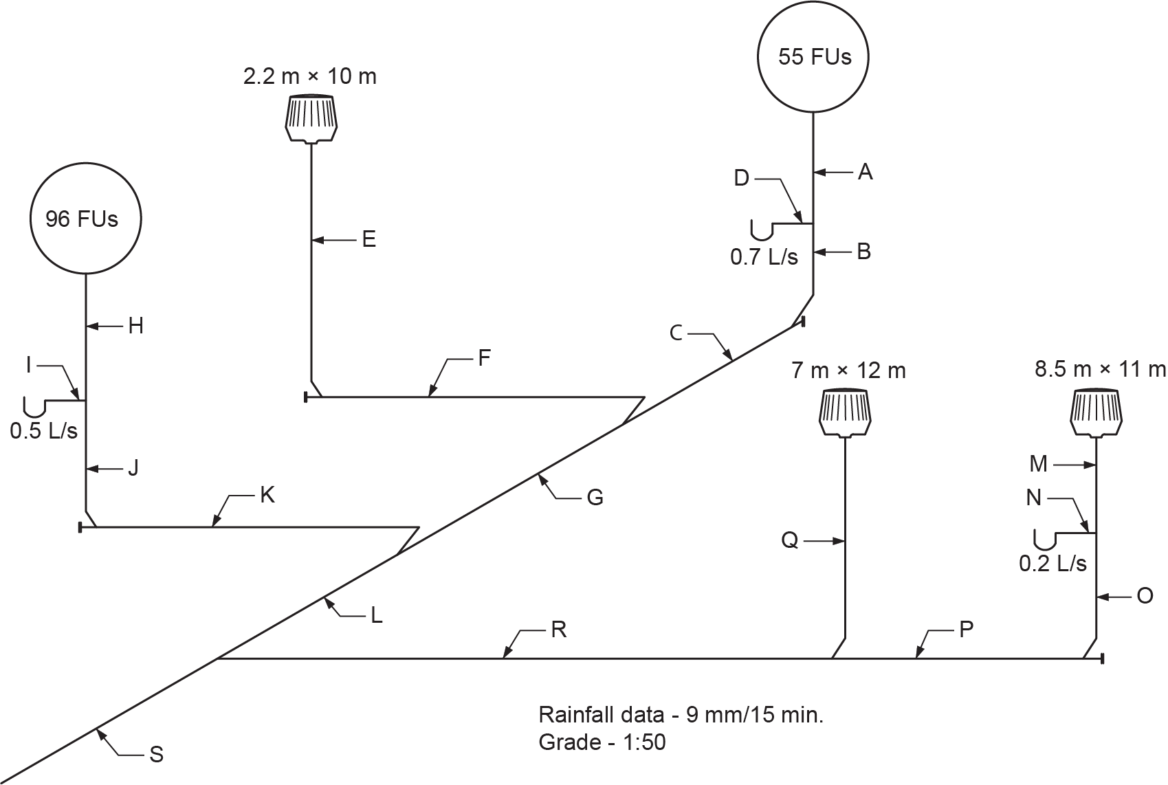
Refer to Figure 7 to see the hydraulic load calculations in Table 7 illustrated on a map of a combined drainage system. Size all horizontal pipe sections as storm, sanitary, or combined building drains using the given grade ratio.
| Label | Name | Leader (m2) | Load | Size (in.) |
|---|---|---|---|---|
| A | SOWS | − | 55 FUs | 3 |
| B | SOWS | − | 77.19 FUs | 3 |
| C | Sanitary building drain | − | 77.19 FUs | 4 |
| D | Trap arm fixture drain | − | 22.19 FUs | 3 |
| E | RWL | 22 | 198 L | 2 |
| F | Storm building drain | − | 198L | 3 |
| G | Combined building drain | − | 3188 L Sanitary 55 FUs = 2360 L semi or cont. flow 0.7 L/s = 630 L Storm drainage = 198 L |
4 |
| H | SOWS | − | 96 FUs | 3 |
| I | Trap arm fixture drain | − | 15.85 FUs | 3 |
| J | SOWS | − | 111.85 FUs | 4 |
| K | Sanitary building drain | − | 111.85 FUs | 4 |
| L | Combined building drain | − | 3638 L Sanitary 151 FUs = 2360 L semi or cont. flow 1.2 L/s = 1080 L Storm drainage = 198 L |
4 |
| M | RWL | 93.5 | 841.5 L | 2 |
| N | Trap arm fixture drain | − | 180 L | 3 |
| O | RWL | 93.5 | 1021.5 L | 3 |
| P | Storm building drain | − | 1,021.5 L | 3 |
| Q | RWL | 84 | 756 L | 2 |
| R | Storm building drain | − | 1,777.5 L | 3 |
| S | Combined building drain | − | 5,415.5 L Sanitary 151 FUs = 2360 L Semi/Continous flow 1.4 L/s = 1260 L Storm drainage = 1795.5 L |
4 |
Slopes
The slope ratio used with storm drainage systems must be steep enough to provide a flow velocity between 0.6 and 0.9 m/s to avoid excess water retention at the drain location. The NPC states that every drainage pipe with a size of 75 mm (3 in.) or less shall have a downward slope in the direction of flow of at least one in 50 ([latex]\tfrac{1}{3}[/latex] in./ft.), with the exception of a storm and combined building drain or sewer larger than 75 mm. For example, a 100 mm (4 in.) storm building drain or storm building sewer is permitted to be sloped at 1:100 ([latex]\tfrac{1}{8}[/latex] in./ft.).
Fittings
The fittings used in storm drainage systems are the same DWV type used in sanitary drainage systems. However, expansion and contraction are a concern when a roof drain joins into a leader. The NPC requires that the roof drain be tightly connected to the leader and that provisions be made for expansion and contraction. You could accomplish this using an expansion joint or loop at the roof drain in the horizontal section of the leader to accommodate the leader’s movement without affecting the roof drain.
Due to a possible surcharge condition during a high-flow event, vertical leaders should be connected to the building drain with single-wye fittings; the use of double-wye fittings should be avoided.
Orientation
Quite often, the roof drain and the leader location do not line up, and an offset is required. The NPC has certain requirements with regard to leader offsets, as stated in Clause 2.4.9.5.:
- There is no requirement to change the size of the leader with a nominally horizontal offset if the offset is located immediately under the roof and is not more than 6 m (19 ft 8 in.) long with a 1:50 minimum slope.
- If the horizontal offset is more than 6 m long, the leader shall be sized as a storm building drain using Table 2.4.10.9.
Appliance and Fixture Connections to a Storm Drainage System
In Clause 2.4.2.1.(1), the NPC states certain limitations on the type of appliances or fixtures that may drain into a storm drainage system. The items that may be connected are:
- A drinking fountain, provided that if it is subject to backflow, a backwater valve is installed in the drinking fountain waste pipe.
- Drainage pans from HVAC equipment, provided that if it is subject to backflow, a backwater valve is installed.
- A floor drain, provided that it is located where it can only receive clearwater waste or stormwater.
Fixture drains from the following appliances or fixtures may be directly connected to a common pipe:
- Fixtures used to display, store, prepare or process food and drinks
- Sterilizers
- Appliances that use water as heating or cooling mediums
- Water-operated devices
- Water-treatment devices
- Drains or overflows from a water or heating systems
Code states that the first two fixture types (the display case and the sterilizer) should drain into a sanitary drainage system because they are not considered clearwater waste. The following four types of fixtures could drain to either a sanitary or storm drainage system because they are considered to discharge clearwater waste.
This common pipe must be indirectly connected using an air break above the flood level rim of a fixture directly connected to a drainage system. When this provision is employed, the indirectly connected pipe must pass full-size through the roof if it receives discharge from three or more storeys.
Flow-Control Roof Drains
Controlled-flow systems collect rainwater on the roof and release the flow slowly to the drainage system. These systems can provide significant installation savings because they require smaller “flow-control” roof drains and smaller-diameter piping. These systems also reduce the impact on the sewage treatment plant from combined storm/sanitary sewer systems in locations where they are allowed.
In Clause 2.4.10.4.(2), the NPC states certain requirements when flow-control roof drains are employed and water is allowed to pond on the roof. Flow-control roof drains may be installed provided that:
- The maximum drain down time of the stored water does not exceed 24 hours.
- A structural engineer has deemed that the roof structure design is able to carry the weight of the stored water.
- The flow-control roof drains are located not more than 15 m (49 ft) from the edge of the roof and not more than 30 m (100 ft) from adjacent drains.
- There is at least one flow-control roof drain installed for every 900 m2 (9,687 ft2) of roof area.
- One or more overflow scuppers are installed along the perimetre of the building not more than 30 m (100 ft) apart. The overflow scuppers must provide protection so that up to 200% of the local 15-minute rainfall intensity can be drained, with the maximum depth of controlled water limited to 150 mm (6 in.).
Roof Drainage Emergency Overflow and Scuppers
Emergency overflow systems are referred to as secondary drainage systems and may be either scuppers, which allow the entrapped rainwater to overflow the roof, or a separately piped drainage system. The secondary piping system is installed separately from the primary system and discharged to an approved disposal point, preferably above grade, so building personnel can see that the primary drainage system is blocked.
In Clause 2.4.10.4.(2)(c), the NPC states certain regulations when installing these systems. When the height of the parapet wall is more than 150 mm (6 in.) or exceeds the height of the adjacent wall flashing, emergency roof overflows or scuppers shall be provided along with a minimum of two roof drains serving the roof. The requirements for the scupper locations and spacing are the same as the scupper requirements for flow-control roof drains, as mentioned earlier.
Prohibitions
The NPC has a number of prohibitions when installing storm drainage systems, including that it is prohibited to:
- Install a combined building drain unless it has been proven by past performance to be acceptable in some localities. If this is the case, then the installation of a combined building drain may be accepted.
- Install a sheet metal leader inside a building.
- Directly connect an overflow from a rainwater tank to a storm drainage system.
- Have a vertical soil or waste pipe conducting both sewage and stormwater.
- Have unused open ends in a drainage system, and when a dead end is provided, it must be graded so that it cannot retain water.
Traps
The NPC requires that where a storm drainage system connects to a combined building sewer or a public combined sewer, a trap, known as a building trap, shall be installed between any opening in the system and the drain or sewer. The one exception is that a trap is not required if the opening is the upper end of a leader that terminates at a roof used only for weather protection that is:
- Not less than 1 m (39 in.) above
- Not less than 3.5 m ([latex]11[/latex] ft [latex]5\tfrac{4}{5}[/latex] in.) in any other direction from any air inlet, openable window, or door
- Not less than 1.8 m ([latex]5[/latex] ft [latex]10\tfrac{7}{8}[/latex] in.) from a property line
A floor drain that drains to a storm drainage system shall be protected by a trap. The trap must be located between the floor drain and a leader, storm building drain, or storm building sewer. This single trap may serve all floor drains located in the same room and need not be protected by a vent pipe.
Where freezing conditions could cause storm drainage systems to freeze due to air circulation within the piping, a trap with a cleanout shall be installed in a heated location.
Cleanouts
The NPC has certain construction and location requirements for cleanouts serving DWV systems, as described in Section E-1. Those requirements apply to storm drainage systems as well.
As an example, every interior leader shall be provided with a cleanout fitting at the bottom of the leader, not more than 3 m (9 ft 10 in.) upstream of the bottom of the leader. This requirement is identical to the requirement for cleanouts at the base of a SOWS.
Venting
The NPC does not require venting in storm drainage systems, even if a trap is serving the system in some capacity.
Hangers and Supports
The hangers used must be compatible with the pipe they are supporting. You must use a hanger that will not be detrimental affected by corrosion on the piping. Due to the expansion and contraction effects experienced in storm drainage systems, the support system must always keep the pipe and fittings in proper alignment. A riser clamp should be provided at each floor line to support a leader. At the lower floors, all exterior leaders that may be damaged when installed in parking or truck-loading areas should be adequately supported and protected by sufficient guards.
Spacing
The NPC regulation states the maximum distance between supports and does not differentiate between storm and sanitary drainage piping. Depending upon the type of material you are using and whether the pipe is installed horizontally or vertically, the spacing between supports will vary.
Insulation
Low-temperature liquid flow in the storm interior drainage piping causes condensation to form on the outside of the piping, possibly causing stain damage to the ceilings or, where exposed, drip marks on the flooring. The NPC requires that an internal leader be insulated to protect the building interior from condensation. The insulation type and thermal properties may differ from job to job, so it is important to refer to the job specification requirements prior to installation.
 Self-Test D-3.3: Storm Drainage Code Requirements
Complete Self-Test D-3.3 and check your answers.
If you are using a printed copy, please find Self-Test D-3.3 and Answer Key at the end of this section. If you prefer, you can scan the QR code with your digital device to go directly to the interactive Self-Test.

References
Skilled Trades BC. (2021). Book 2: Install fixtures and appliances, install sanitary and storm drainage systems. Plumber apprenticeship program level 2 book 2 (Harmonized). Crown Publications: King’s Printer for British Columbia.
Trades Training BC. (2021). D-3: Install storm drainage systems. In: Plumber Apprenticeship Program: Level 2. Industry Training Authority, BC.
Media Attributions
All figures are used with permission from Skilled Trades BC (2021) unless otherwise noted.
A type of durable, ribbed metal piping commonly used in stormwater systems such as culverts or detention systems. It must be joined with couplings that align pipes, resist separation, and prevent root or debris infiltration. (Section D-3.3)
A vertical exterior pipe made of sheet metal that conveys rainwater from gutters to the ground. It is permitted for use only above ground and outside a building. (Section D-3.3)
Identifiers that must be cast, stamped, or permanently marked on each pipe or fitting, indicating the manufacturer, weight, class, or quality. These must remain visible after installation to comply with code. (Section D-3.3)
A standard time frame used to express storm drainage load calculations, based on the volume of rainfall (in litres) expected over a 15-minute period. This metric helps determine appropriate pipe sizing. (Section D-3.3)
The amount of rain, measured in millimetres, expected to fall over a 15-minute period in a specific geographic location. This data is obtained from the National Building Code and is critical to calculating drainage loads. (Section D-3.3)
A unit of measure used in sanitary drainage systems to represent the load-producing effect of a plumbing fixture. In combined systems, 1 FU = 9.1 L/15 min when total load exceeds 260 FUs. (Section D-3.3)
The process of determining the correct gutter dimensions based on roof area, local rainfall intensity, and gutter slope. Though sizing is influenced by plumbing code data, installation is typically performed by specialized gutter contractors. (Section D-3.3)
The unit used to express drainage loads in storm and combined systems, aligning volume with a 15-minute rainfall time frame. Helps convert area and rainfall depth into actionable flow data. (Section D-3.3)
A one-way flow control valve installed in a drainage system. Backwater valves are required to protect fixtures and drainage openings installed below grade, such as in a basement, where the possibility exists for the municipal sewage or stormwater systems to become overloaded and force wastewater back through your drains. Backwater valves are also required on
any subsoil drainage pipe that connects into the sanitary drain to protect it from sewage backups. Under normal conditions, it allows the wastewater to drain out of the system, but if a reversal of flow should occur, the valve is forced closed and protects the interior of the building from sewage backup. (Figures 4 and 5, Section D-1.2; Section D-2.3)
An exterior, box-like device or opening in a parapet or wall that collects and drains stormwater from flat roofs. Scuppers serve as emergency overflow systems to prevent water buildup when primary roof drains are blocked. They are often used in combination with parapet walls and flow-control drains. Scuppers must be located no more than 30 m (100 ft) apart and be capable of handling up to 200% of local rainfall intensity when used with flow-control systems. (Section D-3.3)
