D-2.2 Planning Interior DWV System Layouts
The layout process of a DWV system requires the plumber to consider all installation aspects of the system. Because each project is different, it is essential that the installer have a thorough understanding of applicable plumbing codes and the ability to visualize the completed DWV system.
Location of Structure Penetrations
In wood-frame buildings, keep the size and number of penetrations through structural members to a minimum. In a situation where a penetration is required, take care to not cut and notch wood joists and beams in a manner that reduces the strength and load-carrying ability of the structural member.
Regulations restrict the size and location of these penetrations, depending on the type of component. It is important to determine whether the wooden component is load bearing to correctly determine the allowable size penetration that can be drilled or notched. No penetration in the structure should be made until the entire project has been laid out.
When you are planning structural penetrations, note that commercial buildings equipped with fire separations require special considerations. Combustible DWV piping penetrations are permitted in a rated fire separation or a membrane that forms part of a rated fire separation as long as the penetration is sealed by a fire-stop system.
In some instances, sanitary building drains leave the building through a foundation wall due to the elevation of site services. The location and elevation of this penetration should be determined at the time of forming so that blocking or sleeves can be installed prior to the concrete pour, eliminating the need for coring expenses later.
Roof vent terminals should be located where they do not interfere with building aesthetics. In a residential installation, for example, locating the vent terminal on the back slope of the roof as opposed to the front will eliminate sighting from the street. Vent terminals should be located where they are provided with ample air supply and are not susceptible to adverse wind effects. The clearances that must be maintained from occupied spaces and building openings have already been discussed in Section D-1.1: Codes and Standards.
Routing
The location of the major fixture groups determines the preferred location of stacks and branch drains. A thorough inspection of the proposed route is required to identify possible conflicts with structural components and space coordination with other trades. The routing should follow the lines of the building (parallel and perpendicular). This practice will limit bulkhead and ceiling drop installations to accommodate the DWV installation.
When a route is being planned, the plumber must be aware that current building codes do not allow plumbing drains and vents to be installed in the outside walls unless full insulation value can be achieved. This means the wall must be furred (built) out or the piping relocated to an interior space.
When routing drain lines in the ceiling space over sensitive areas, consideration must be given to the possibility of damage caused if there is a blockage that requires cleaning. Drains should be routed far enough away from walls and obstructions, so that the drain-cleaning machine can gain access if needed.
Pipe Supports
Underground piping from the municipal system into your home is installed in dug trenches to a depth below the frost line for your climate, which obviously could vary a great deal depending on your geographical location. The trench should be constructed as narrow as is reasonable to allow proper joining of the pipes and to avoid having to dig below the depth required to support the pipe, as the undisturbed soil is naturally compacted and will not settle over time.
When laying the piping in the trench, the markings on the pipe that indicate the type and class of pipe should face up, and all the joints must be visible until an inspection by the local authority has been done.
Inside the building, the maximum distances between pipe supports are specified in the National Plumbing Code (NPC). The supports must be located to maintain a uniform slope that will not change with time. The pipe supports and structure connections must be able to resist forces due to hydraulic testing and the seismic forces imposed on them. The support locations must not introduce stresses in the piping caused by thermal expansion or contraction, and must isolate the piping from stresses caused by twisting, torsion, or lateral bending in the framing members.
 Self-Test D-2.2: Planning Interior DWV System Layouts
Complete Self-Test D-2.2 and check your answers.
If you are using a printed copy, please find Self-Test D-2.2 and Answer Key at the end of this section. If you prefer, you can scan the QR code with your digital device to go directly to the interactive Self-Test.

Media Attribution
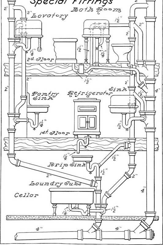
- Figure 1 “Modern” Plumbing in 1907 – Identifier: cu31924015368818, at Flickr, is by Starbuck, Robert Macy, 1844-. This image is an excerpt from Modern plumbing illustrated; a comprehensive and thoroughly practical work on the modern and most approved methods of plumbing construction, found on the Internet archive. It is in the public domain.
Stands for Drain, Waste, and Vent system, which removes wastewater and vent gases from a building, ensuring proper drainage and pressure balance. (Section D-1.3; Section D-2.3)
A hole or opening made in a structural component, like a wall or floor, to allow for pipes, ducts, or other systems to pass through. (Section D-2.2)
A method used to seal penetrations in fire-rated walls or ceilings to prevent fire from spreading through the openings. (Section D-2.2)
The opening or vent located on the roof of a building, allowing gases and odors to escape from the plumbing system. (Section D-2.2)
The planning and installation of plumbing pipes in a building, taking into account obstacles and the structure to ensure smooth, efficient plumbing connections. (Section D-2.2)
A barrier or wall built within a building that may require plumbing installation adjustments for the DWV system. (Section D-2.2)
A method of lowering pipes or ducts from the ceiling to accommodate plumbing or electrical systems. This is done when it's necessary to route systems through spaces where the ceiling is lower or obstructed. (Section D-2.2)
The depth below the ground surface where the soil freezes in cold climates. Pipes must be installed below this line to avoid freezing. (Section D-2.2)
Structures or brackets that hold pipes in place, ensuring they are properly aligned, supported, and maintained at the correct slope for drainage. (Section D-2.2)
The forces exerted on structures during an earthquake, which plumbing systems must be designed to withstand. (Section D-2.2)
