D-2.1 Types of DWV Drawings
A plumber should be competent in creating and interpreting drawings. Time and materials can be wasted if a project is not planned well. You may not always be provided with a set of piping drawings, so you must be able to extract all required information about the piping systems from general architectural drawings. This is usually the case on smaller jobs.
You must know how to read drawings in order to work efficiently with other trades. By clearly envisioning the location of structural members, wiring, and ductwork, you can spot possible conflicts in the piping system and solve problems before you start to install the piping.
Construction Drawing Types
To identify their purpose, drawings are divided into classifications. On very large projects, such as high-rise office towers, it would be impossible to place all the pertinent information on one drawing. So, several types of drawings are made, each with specific information. The types of drawings include:
- Plot
- Architectural
- Structural
- Mechanical
- Electrical
- Shop
- As-built
Plot Plan
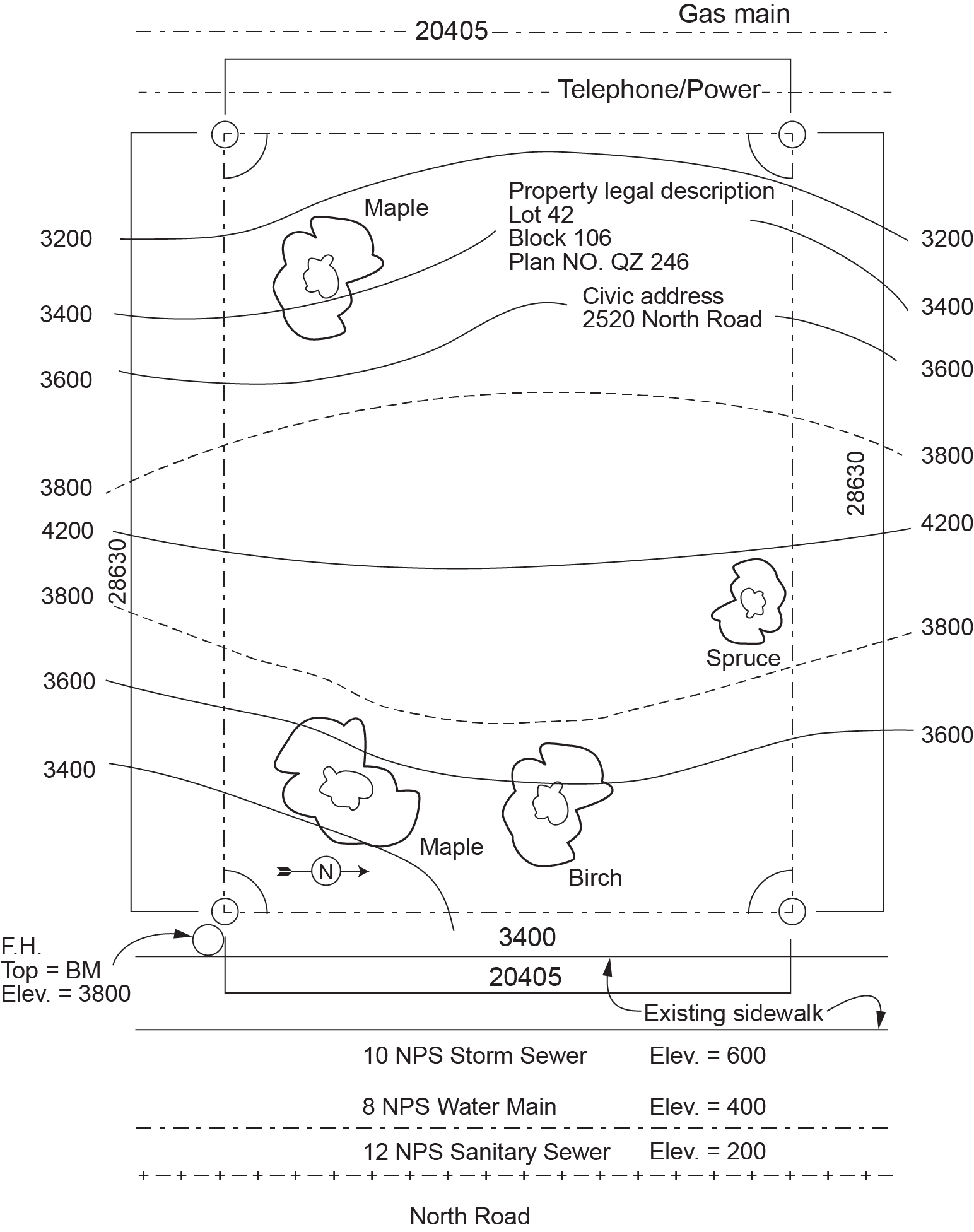
Plot plans are usually shown on the first sheet of a set of drawings. The property line appearing on the plot plan shows the size and shape of the lot. Public utility mains, or at least the points of hookup to them, are usually shown on plot plans. Included among these utilities are potable water, gas, sanitary and storm sewer mains, and electrical and telephone lines.
Each contour line on the plot plan shows points of equal height or elevation on the lot. Every contour line is marked with a particular height, say 3.8 m or 44 ft, meaning that every point on that line is 3.8 m or 44 ft above a chosen point of reference. This point of reference may be sea level, an engineering elevation marker, or simply a convenient assumed elevation, such as 100 m or 100 ft. By comparing the heights between different contour lines, you can determine the slope of the lot at any given point. In addition to contours, plot plans show the heights of specific points on the lot, such as the corners of the lot or the locations of trees.
Figure 1 is a plot plan in metric.
Site Plan
The site plan is a plot plan with a basic outline of the building superimposed on it. Figure 2 shows a site plan based on the plot plan of Figure 1. The site plan clearly shows the building’s location and its services. The storm sewer, water main, and sanitary sewer are on the east side of the property. Their diameters are given in the legend as 10 NPS, 8 NPS, and 12 NPS, respectively.
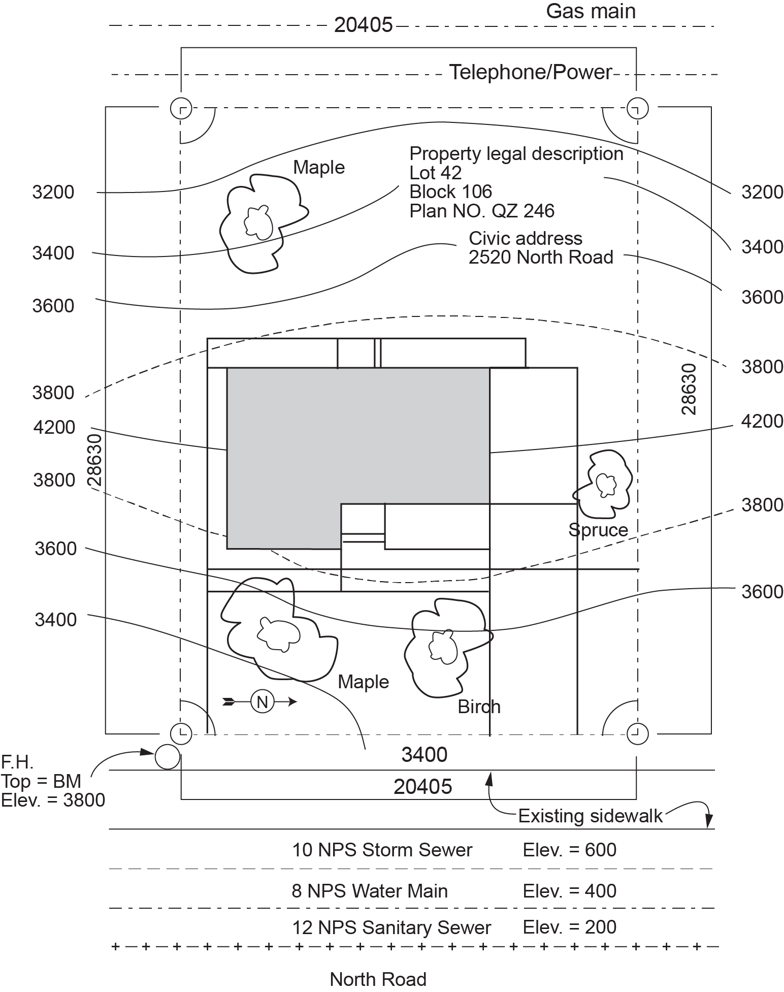
The plot plan and site plan show the location of public utilities. This information will help us identify where building drains and supply pipes must be run to connect with municipal services (the storm sewer, sanitary sewer, water main, and gas main).
The site plan shows the horizontal distance of these utilities from the proposed building, and the elevation difference between the public utilities and the basement. Finding the elevations of the utilities is a simple matter: the elevations of each utility are shown in the notes or written beside the utility on the drawing.
To determine whether the utilities can operate on gravity or if they require a pump, compare the elevations of the utilities to the basement elevation. To find the basement elevation, you will need to consult more than one drawing. The site plan shows the first-floor elevation, and an elevation drawing shows the distance between the first floor and the basement. To get the basement elevation, subtract the distance between floors from the first-floor elevation.
To calculate the amount of pipe you need, you need to know the horizontal and vertical distances of the utilities from the house. You also need to pay attention to the location of the property line. The city usually supplies pipe from the utilities to the property line, while the piping contractor supplies pipe from the building to the property line.
To install a septic tank, you need to check the location of the properly line because septic tanks and disposal field piping cannot be located within a certain distance from neighbouring properties. You also need to check the contour lines. Septic tanks should be installed where the grade is quite level.
Landscape Plan
The landscape plan may or may not be part of a building contract. The landscape plan is based on the site plan. A landscape architect may design the landscape and show all the recommended trees, shrubs, flowers, grass, and structures (fences, seating, walkways, etc.) on a landscape drawing. Landscaping is important for the final appearance of a building. If plumbers will be installing lawn sprinkler systems, the landscape plan will be used to design the layout of the system and the types of sprinklers used.
Architectural Drawings
The architectural drawing is the main drawing of a building. It presents the overall design of the building or structure to be built. It details all the finishing of the building and the materials used. The drawings include floor plans, elevations, sections, and details. An architectural drawing is usually indicated by an “A,” which precedes the drawing page number (e.g., A-4).
When somebody wants a building built, they hire an architect (or designer) to design it. The architect finds out what type of building the customer has in mind and what the requirements are. The architect then makes a rough design for the customer’s approval. When the details of the design have been agreed upon, the architect draws a complete set of plans for the building. If the building is fairly simple, like most houses, all information can be placed on one set of drawings, from which all tradespeople can work. Houses are often built from stock plans that the owner or contractor has purchased from a design company.
Floor Plan
The floor plan is a plan view of one floor. Architectural floor plans generally show the layout of rooms, dimensions, types of materials used, equipment, fixtures, and appliances. Figure 3 shows a typical floor plan.
Piping plans are always developed from floor plans by either the piping contractor or the engineer. There are several things to consider when you plot piping routes from a floor plan. The locations of plumbing fixtures, components, floor drains, and vertical drainage pipe stacks play a role in determining where a pipe is routed. You need to check the floor plan for doorways and windows because you need to install the pipe around these features.
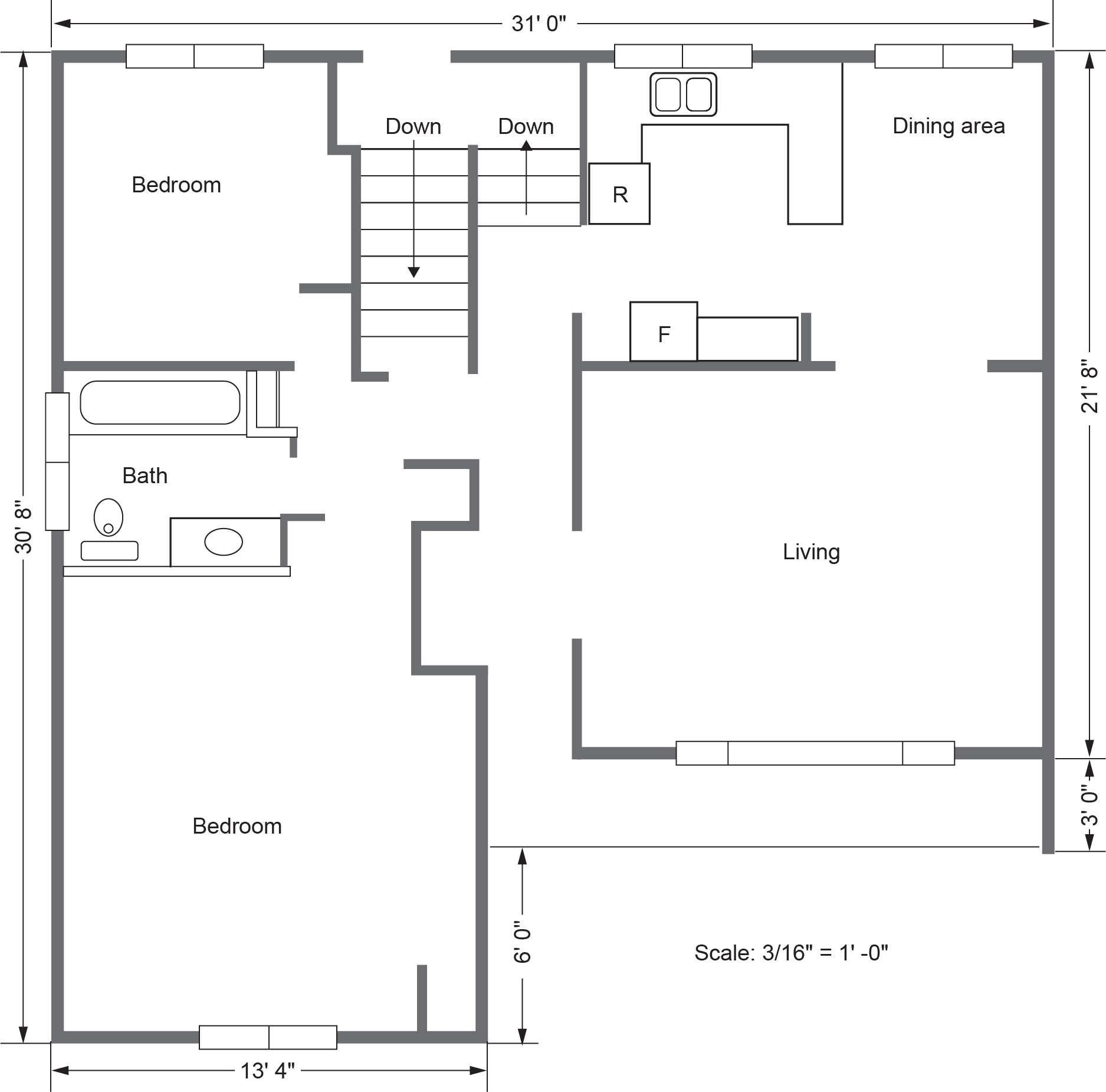
Plumbing fixtures are shown as locations for drainage, waste, and vent (DWV) pipes, as well as for hot and cold water supply lines. Piping should be convenient to the fixture and concealed in walls, ceilings, floors, or in unused spaces where they do not conflict with other installations.
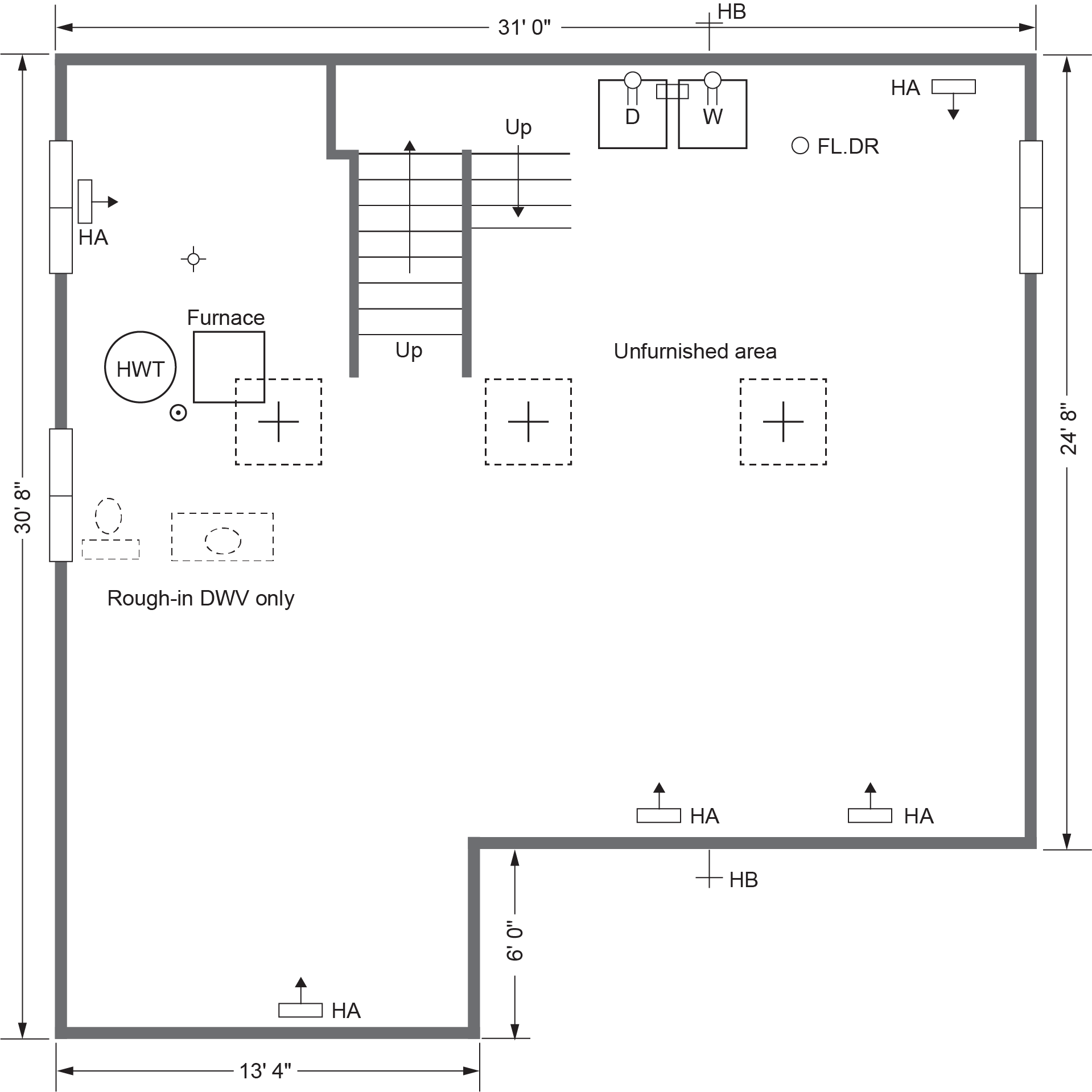
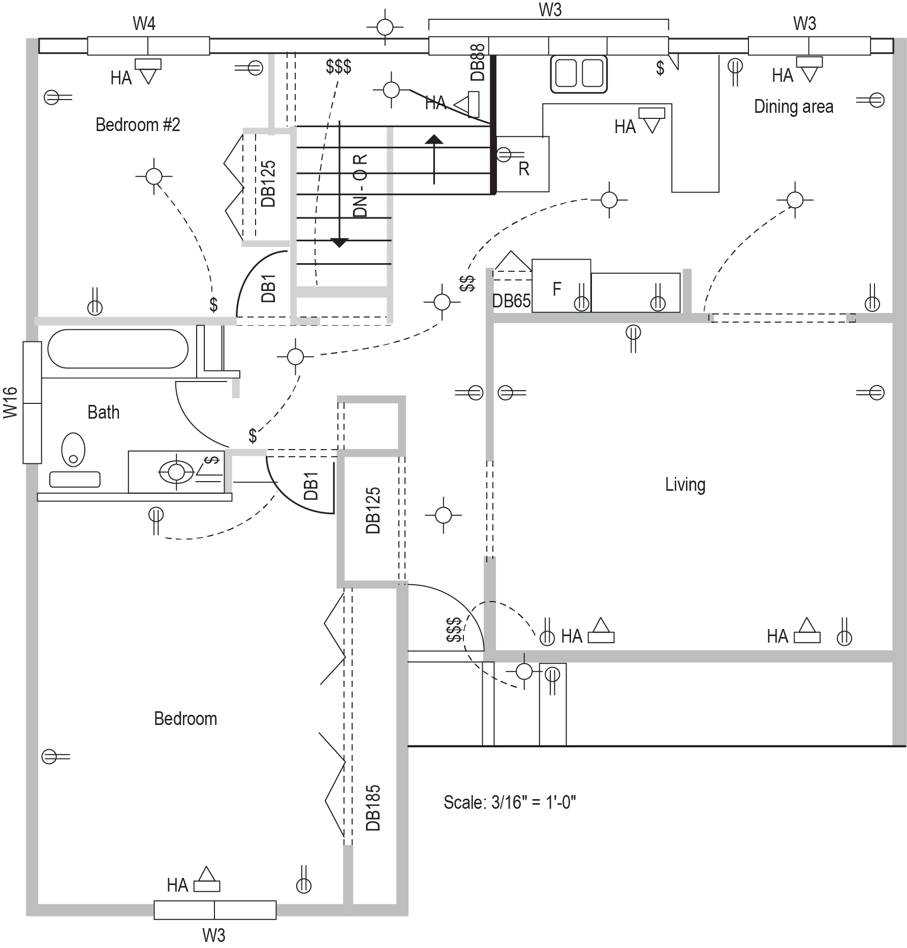
Figure 4 is the lower floor plan of the same house. It indicates the locations of the clothes washer, the floor drain, and the fixtures for the roughed-in half bath as well as the hot water tank and hose bibbs. You must coordinate the DWV and supply piping to these fixtures with those on the upper floor.
Reflected Ceiling Plan
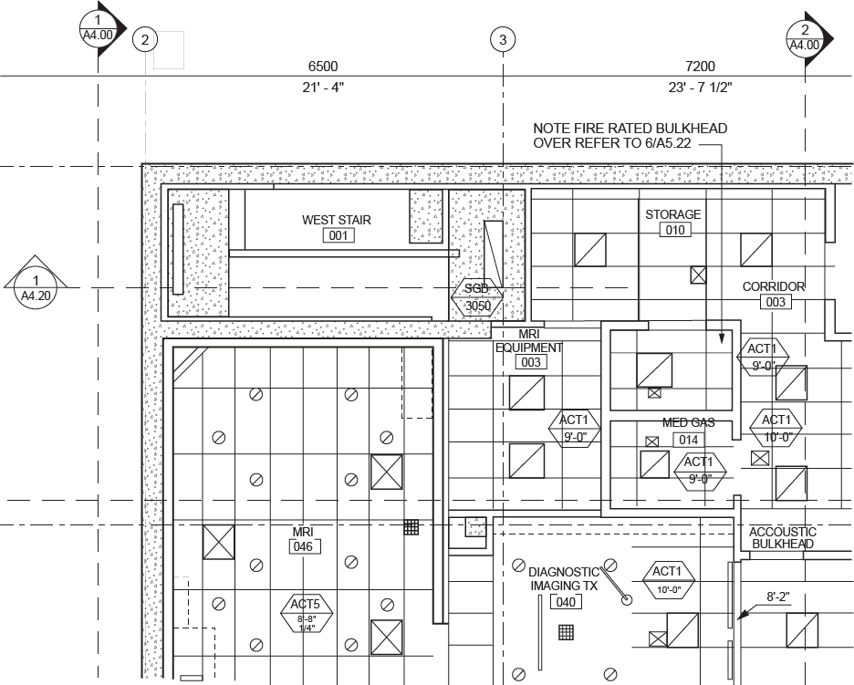
A reflected ceiling plan shows an overhead plan view of a building ceiling, as if you were looking at it using a mirrored floor. These typically show tile ceiling layouts, light fixtures, speaker locations, diffuser locations, smoke detectors, and sprinkler locations, as related to the structural reference points and the floor plan. Figure 5 shows a corner portion of a reflected ceiling plan.
Elevations
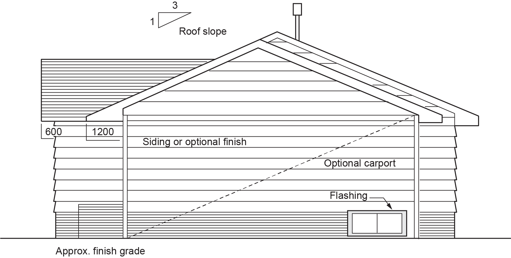
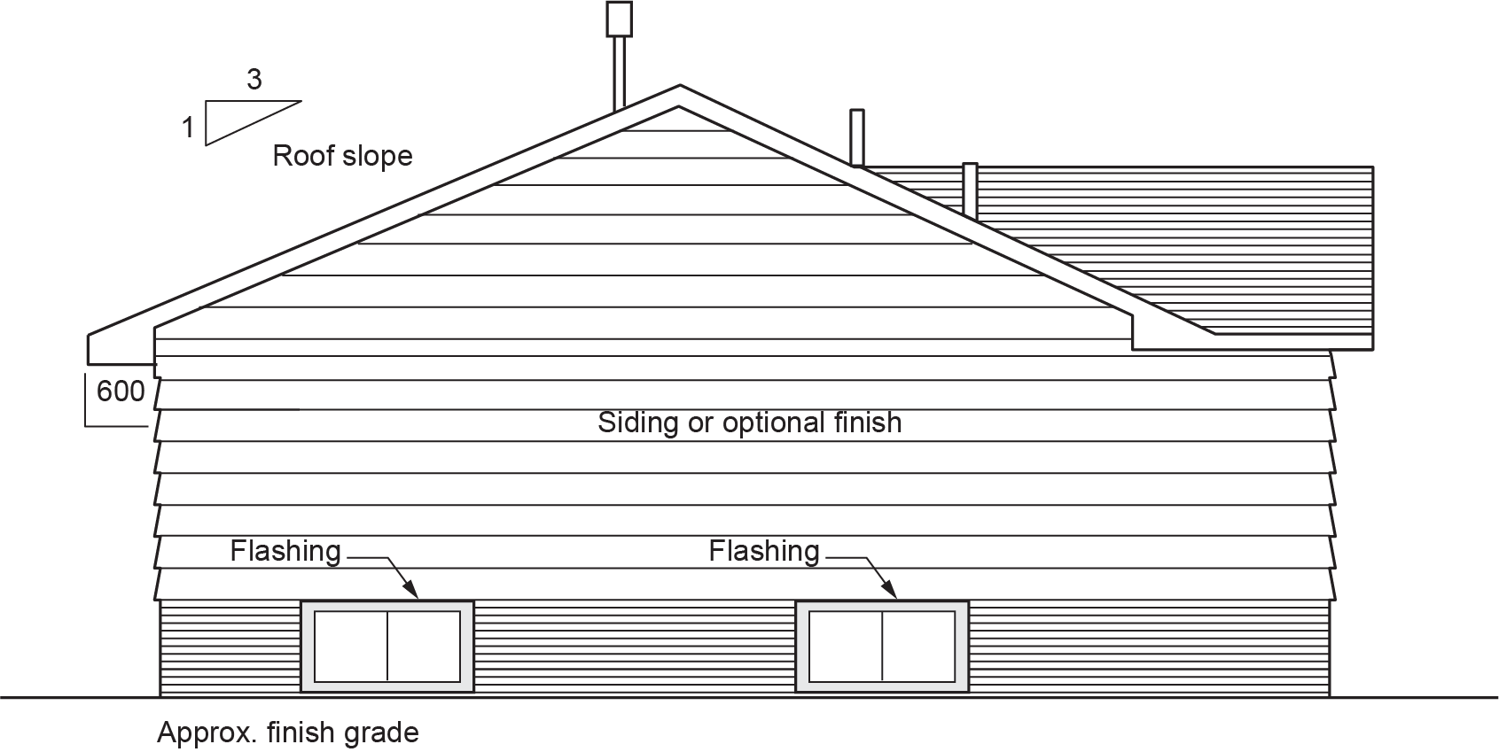
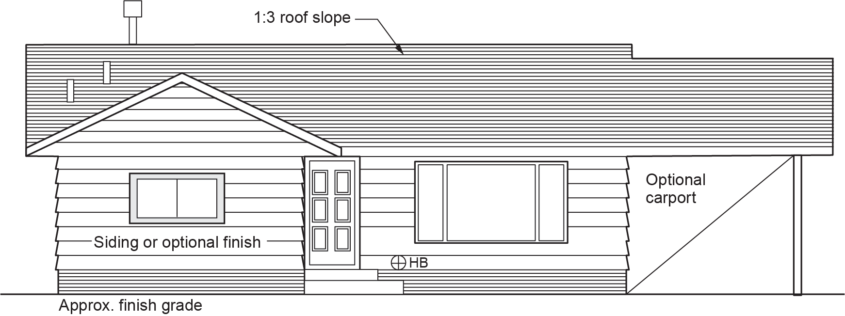
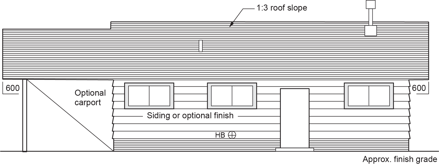
Elevation drawings display the finished exterior view of the front, back, or side of a building. Together, the front, back, and two side elevation drawings give a clear idea of what the building will look like on completion. Locations and type of all wall openings and roof penetrations are shown on elevations. Elevation drawings also show the slope of the roof. A set of all four elevation drawings is shown in Figures 6 through 9. Consult the elevation drawings to calculate the total length of vertical piping needed to complete a job.
A floor plan will show a symbol for a vertical drainage stack. However, the floor plan does not indicate how long the drainage stack must be. Calculate the length of the drainage stack by checking the height of the building on the elevation drawing.
Sectional Views
Sectional views give information about wall construction, the exterior wall finish, and the interior wall finish. Check these drawings for potential obstructions or conflicts for all locations where piping must penetrate walls.
Details
The details given on the floor plan give precise information on the location of sinks, showers, lavatories and other fixtures. The details on elevation drawings provide information on the heights of these fixtures. You need to know the heights of fixtures in order to correctly rough in the piping. Detailed drawing will take precedence over the regular drawings.
Structural Drawings
A structural drawing is required for buildings other than houses. It can be a simple one-page drawing or can include many pages of drawings. The structural drawing is usually indicated by an S, which precedes the drawing page number (e.g., S-3).
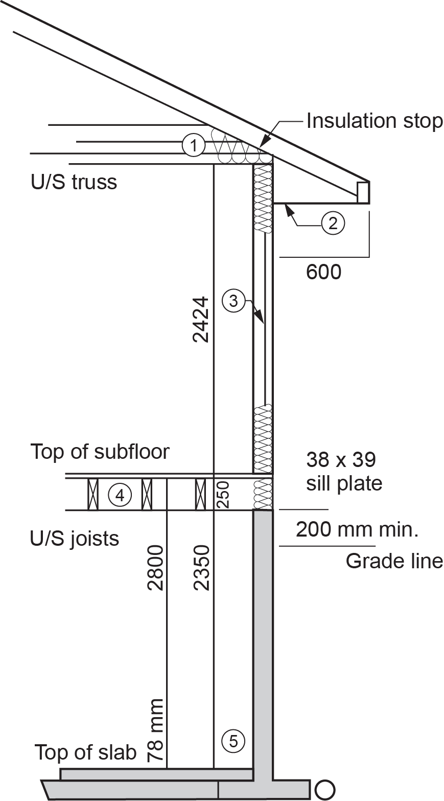
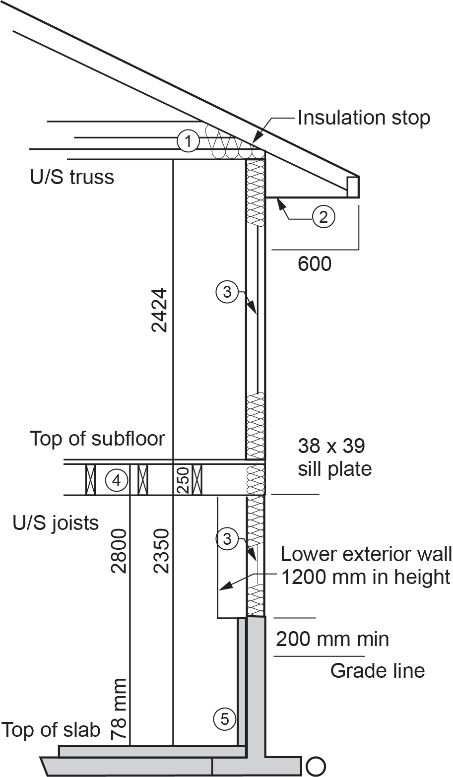
Most structural drawings are sectional views. The structural drawing gives information about the size of beams and girders, the reinforcing steel design, and the size and shape of structural members. It also details the materials to be used and the required strengths of concrete. This drawing is prepared by a structural engineer hired by the architect to design all the structural components of the building. Figures 10 and 11 show two typical structural drawings of wall cross-sections.
Mechanical Drawings
The mechanical drawing (or climate control plan) is used to identify and locate services for plumbing, heating, air conditioning, duct work, etc. The mechanical drawing is indicated by an M, which precedes the drawing page number (e.g., M-5).
The mechanical drawing is based on the floor plans of the architectural drawings. The architectural details are removed so that they do not interfere with the mechanical details. Sometimes, other drawings are required to complete the mechanical drawing. If there is a great deal of mechanical information, the drawing may be split into two drawings, with plumbing details on one and heating and air conditioning information on the other. In that case, the drawings are called plumbing plans and heating plans. They may also have a separate sprinkler drawing designated by F, FP, or SP.
For a small residential building, separate mechanical drawings are not usually included, and the main mechanical equipment locations will simply be shown on other drawings. For example, in the building drawing we have been looking at, the furnace location is shown in Figure 4 and the heating registers (hot air outlets) and cold air return are included on the electrical drawing in Figure 12.
Electrical Drawings
The electrical drawing identifies and locates services for the building’s electrical system. The electrical plan is based on the floor plan. It shows the layout of wiring for lights, switches, outlets, and electrical panels. It also shows services for low-voltage systems, such as hydronic heating controls, telephone, cable television, and inter-communication network.
On large commercial buildings, factories, and high-rise office towers, the electrical services can be complicated. The electrical drawing is designed by an electrical engineer. It is indicated by an E, which precedes the drawing page number (e.g., E-2). A typical electrical plan is shown in Figure 12.
The locations of all outlets, fixtures, and controls are shown on the electrical plan using electrical wiring symbols. A line of long dashes separated by dots indicates that a fixture and a switch will be connected by wiring. However, the dot-dash does not show the exact path of the wiring through the floor or ceiling. For example, the actual wiring from the dining area light switch to the lighting fixture might run along the wall and then perpendicular to the wall, instead of following the line shown. Plumbers can usually avoid the locations of electrical parts without any difficulty or inconvenience.
Shop Drawings
Shop drawings are used by prefabrication shops for making structural components. For example, a prefabrication shop producing steel columns for a building will take the information from the structural drawings and make detailed shop drawings that show the sizes and dimensions of all the columns. The shop drawings are then sent to the building contractor for approval of the sizes, dimensions, and quantities of each type of column. When the drawings have been approved, the fabricator starts production. Items such as beams, girders, trusses, and other fabricated members require that shop drawings be made before production starts.
As-Built or As-Constructed Drawings
In commercial buildings, changes are often made during construction to deal with conflicts discovered or changes made by the owner or architect as work proceeds. Any deviations from the original as-designed drawings must be documented on drawings. The terms as-constructed and as-built are often used interchangeably as they both refer to a drawing that indicates deviations from the as-designed drawings. These drawings are based on information provided by the installation contractor, therefore, the architect is not responsible for the information.
On some projects, the two terms might mean different things. For example:
- “As-constructed”: the defect and deviation to the designed model occurring during construction.
- “As-built”: the record drawings and documentation defining deviation to the designed information occurring during construction at the end of the project.
Typically, the contractor is required to make red-line markings on the original construction drawings to indicate any changes as work progresses. For example, when services are buried under a concrete slab or hidden behind a wall, the owners of the building often ask the sub-trades, such as plumbers and electricians, to provide detailed drawings of the exact location of the services that have been buried. That way, if there is a problem with the services, the locations of the hidden services are quickly and correctly identified.
These red-line drawings are delivered to either the general contractor or the architect, who prepares the final as-built drawings. These drawings can be vital for the proper maintenance or repair of the building’s systems.
Drawing Parts
To efficiently read drawings, you will need to be able to identify some of the common general parts of a drawing, including:
- Title block
- Scale
- Key plan
- North arrow
- References
- Schedules
- Notes
- Flow diagrams
Title Block
The title block contains:
- Job title (including the name and nature of the project, the name of the owner, and the site address)
- Name of the architectural or engineering firm
- Date of drawing and date of completion
- Job number
- Initials of drafter and checker
- Drawing number
- Scale of the drawing
The drawing number consists of a letter (either A, S, M or E) and a number. The letter refers to the type of drawing:
- A = Architectural
- S = Structural
- M = Mechanical
- E = Electrical
For example, the drawing number A1 of 4 would be the first sheet of the four architectural drawing sheets.
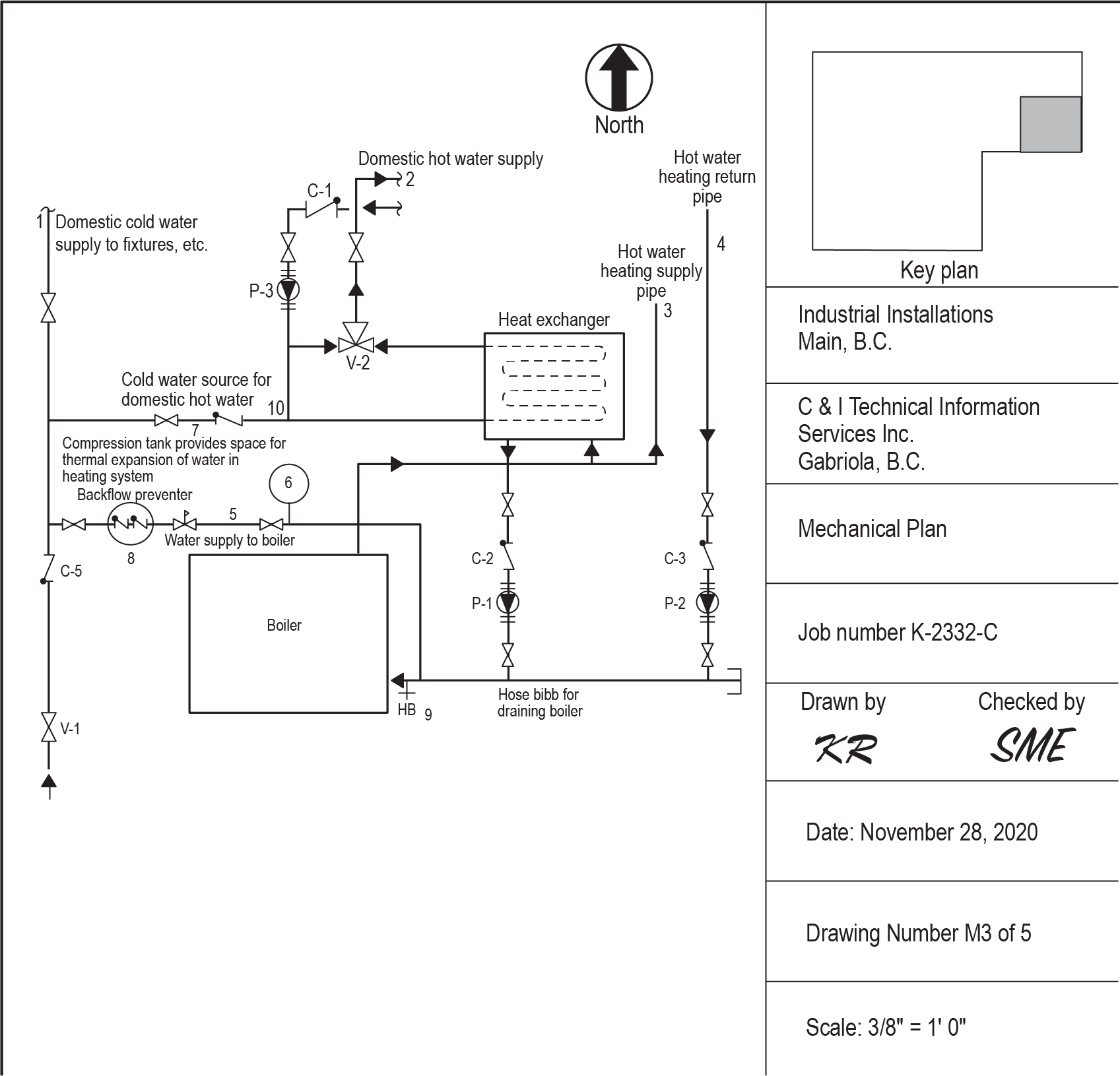
Figure 13 shows a piping drawing with a title block. The upper left portion of the drawing is a plan view, simply called a plan. This drawing sheet is numbered M3 of 5, which indicates it is the third sheet of the five mechanical drawings.
Scale
The scale included in the title block of Figure 13 means that all views on the sheet are drawn to a scale of [latex]\tfrac{3}{8}[/latex] of an inch equals one foot. ([latex]\tfrac{3}{8}[/latex] in. = 1 ft-0 in.).
Key Plan
If a plan drawing is not of an entire floor of a building, a key plan is usually placed near the title block to indicate which part of the floor is shown. The key plan is a miniature outline of the entire floor, with the plan view section hatch-marked or shaded in. A key plan is included in Figure 13.
North Arrow
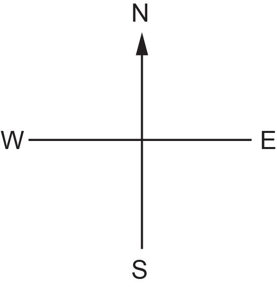
The arrow to the left of the key plan at the top right of Figure 13 shows which direction is north in relation to the building. This north arrow symbol is only used for plans on drawings. It is not used to orient any elevation or sectional views that may be on the same sheet. The direction symbol in Figure 14 is sometimes used in place of the north arrow symbol shown in Figure 13.
References to Other Drawings
Other drawings may be produced for architect’s drawings and show details of exterior walls or details of structural or mechanical drawings. To clarify and expand upon the information shown on a plan, it is common practice to include other drawings, such as a section or elevation drawing. These drawings show details or views of the system from other directions. Elevation drawings may be considered horizontal views of a system, while sections contain part of an elevation cut off at the reference markers.
Elevation References
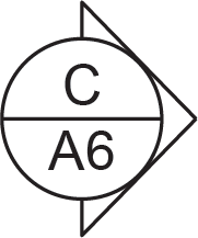
The elevation reference symbol is shown on a plan view and indicates that an elevation drawing showing a vertical cross-section of the building at the point indicated by the symbol arrow has been prepared. The letter in the top half of the symbol identifies the elevation. The bottom half indicates the page on which the elevation drawing may be found. The symbol in Figure 15 indicates that Elevation C is shown on page A6 (one of the architectural drawings).
Section References
A section reference symbol, as in Figure 16, is used to indicate that a section drawing rather than an entire elevation has been prepared. The symbol appears beside any part of a building plan that is shown in sectional view on another drawing sheet. The letter in the top half of the section reference symbol identifies the section. The number in the bottom half shows the page on which the sectional view can be found. The long and short dashed lines indicate which part of the plan is shown in the sectional view, and the arrows show the direction of the view. The section drawing appears on a different page, as indicated by the bottom of the circle. The symbol in Figure 16 indicates that Section B may be found on page A5 and that the drawing presents the section you would view facing to the right.

Detail References
A detail reference symbol, as in Figure 17, appears beside a part of a building plan that is drawn in detail at a larger scale on another page. The number in the top half of the detail reference symbol is the detail number. The number in the bottom half is the page on which the detail drawing can be found. This page number is usually a letter and number combination.
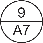
References to detail drawings shown on the same page use the symbol in Figure 18. The detail drawing will be labelled with the number shown in the top half, and the bottom half is left blank to indicate “this page.”
Notice that the details are referenced by numbers, whereas sections and elevations are referenced by letters.
Schedules
A schedule is a convenient method of listing variable conditions on drawings so that similar information can be found in one handy location. For example, an architectural drawing may contain a door schedule that shows the type, size, style, drawing reference number, etc., of all the doors on a plan. Table 1 is a pump schedule that lists all circulation pumps used in the heating installation shown in Figure 13.
| Model No. | Flange Pipe Size (in.) | Face-to-Face Flange Length (in.) | HP | Volts | Phase |
|---|---|---|---|---|---|
| P3S25 | 0.75 | 6.5 | 0.08334 | 115 | 1 |
| P1H32 | 1.25 | 8.5 | 0.1667 | 115 | 1 |
| P2S34 | 1.5 | 8.5 | 0.1667 | 115 | 1 |
Notes
Notes are written descriptions of the materials, equipment, valves, instruments, etc., shown on a drawing. The notes can be placed beside the symbol being described, or they can be numbered and listed in a separate area to prevent crowding in the drawing.
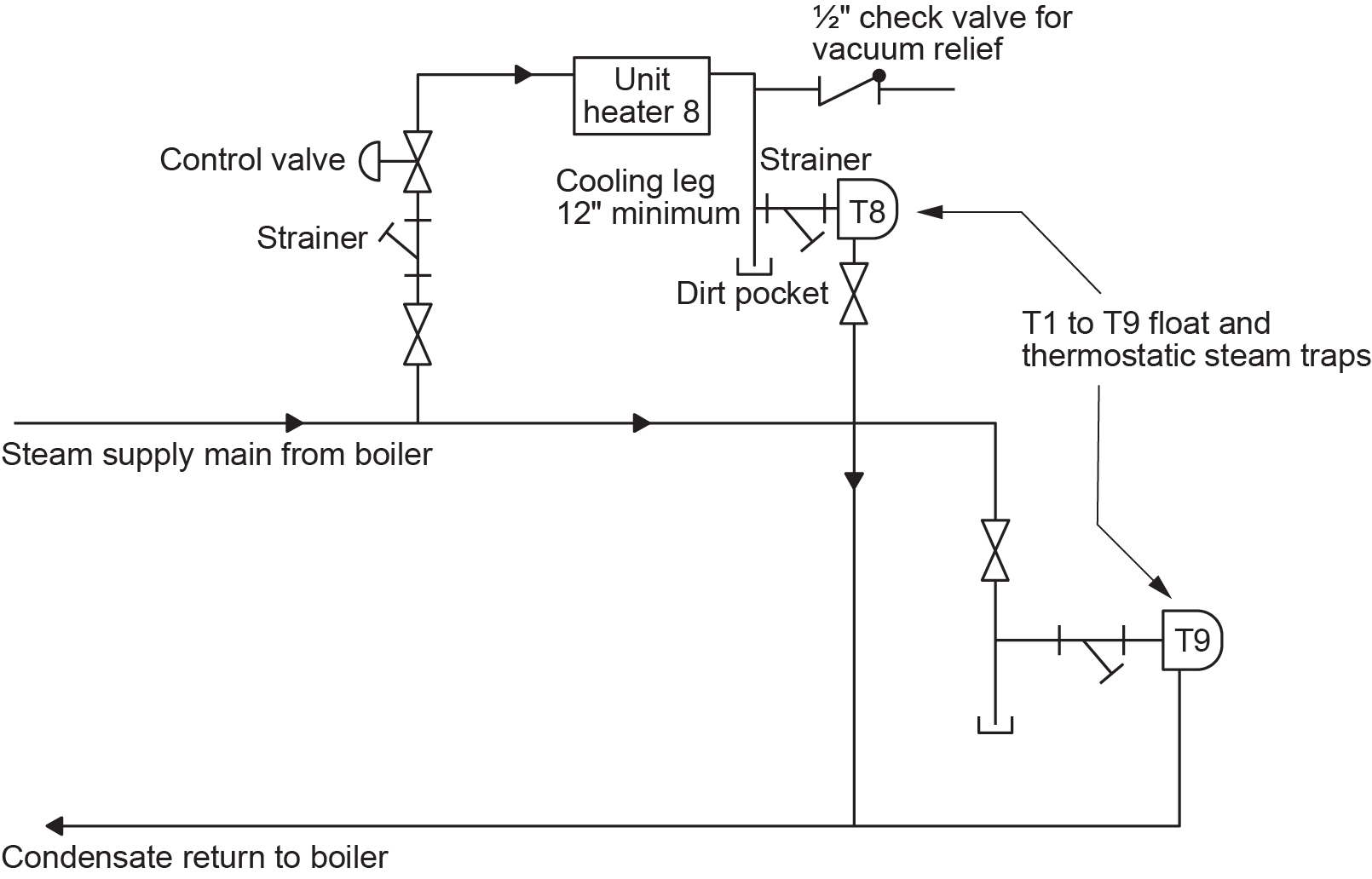
Figure 19 is a flow diagram that contains notes. Some notes are listed with reference numbers, while others are inserted beside the objects described.
 Self-Test D-2.1: Types of DWV Drawings
Complete Self-Test D-2.1 and check your answers.
If you are using a printed copy, please find Self-Test D-2.1 and Answer Key at the end of this section. If you prefer, you can scan the QR code with your digital device to go directly to the interactive Self-Test.

References
Skilled Trades BC. (2021). Book 2: Install fixtures and appliances, install sanitary and storm drainage systems. Plumber apprenticeship program level 2 book 2 (Harmonized). Crown Publications: King’s Printer for British Columbia.
Trades Training BC. (2021). D-2: Plan DWV systems. In: Plumber Apprenticeship Program: Level 2. Industry Training Authority, BC.
Media Attributions
All figures are used with permission from Skilled Trades BC (2021) unless otherwise noted.
A drawing showing the size and shape of the property lot, including utilities and contour lines to determine the slope of the land. These are usually shown on the first sheet of a set of drawings. (Section D-2.1)
A drawing that shows the layout of the building and how it fits on the land, including things like roads, utilities, and the property boundaries. It is a plot plan with a basic outline of the building superimposed on it, which helps understand the location and surroundings of the building. (Figure 2, Section D-2.1)
Elevations show height differences between a building and nearby utilities, like water and sewer lines. They help determine if pipes will use gravity or need a pump to connect to municipal services. This information is found in drawings and notes, helping with the correct placement of pipes and septic tanks. (Section D-2.1)
Vertical views of a building's outside, showing details like the roof slope and wall openings. It also displays the distance from the first floor to the basement. To find the basement elevation, subtract the space between floors from the first-floor elevation. (Section D-2.1)
A drawing that shows the design and layout of the outdoor areas around a building, like gardens, walkways, and trees. It helps plan how the land will look and be used. (Section D-2.1)
the main plan of a building that shows its design, layout, materials, and finishes. It includes floor plans, elevations, sections, and detailed views to guide construction. These drawings are usually marked with an “A” followed by a page number (e.g., A-4). (Section D-2.1)
A horizontal view of one floor of a building, showing room layout, dimensions, materials, and fixture locations, critical for determining piping routes. (Section D-2.1)
A plan showing the layout of the ceiling, including light fixtures, sprinklers, and diffusers, as if viewed from below. (Section D-2.1)
Drawing showing a cut-through of a building to provide detailed information about wall construction and other interior elements (exterior and interior wall finish). Check these drawings for potential obstructions or conflicts for all locations where piping must penetrate walls. (Section D-2.1)
A drawing that shows the building’s framework, including the foundation, beams, and columns. It helps builders know how to build the building to make it strong and safe. The structural drawing is usually indicated by an S, which precedes the drawing page number (e.g., S-3). (Section D-2.1)
(climate control plan); A type of drawing that shows the details of a building’s heating, cooling, plumbing, and other mechanical systems. It helps understand how these systems are set up. (Section D-2.1)
Drawings that show the layout of the electrical system in a building, including lights, switches, outlets, and electrical panels. They also show systems for heating, phone lines, and cable TV. Based on the floor plan, these drawings are created by an electrical engineer and are marked with an "E" before the drawing number (e.g., E-2). (Section D-2.1)
A detailed drawing created by the builder or contractor and used by prefabrication shops that shows how a specific part of the building will be made or installed, like custom furniture or a special part of the building. (Section D-2.1)
The defects and deviations from the original design that occur during the construction process. (Section D-2.1)
The record drawings and documentation defining deviation to the designed information occurring during construction at the end of the project. (Section D-2.1)
The part of a drawing that contains the project title, drawing number, scale, date, and other key project details. (Section D-2.1)
The ratio used to shrink or enlarge a drawing while keeping proportions accurate. (Section D-2.3)
A small map on a drawing (usually near the title block) showing the location of the area depicted, especially if the drawing is of part of a larger structure. (Section D-2.1)
A symbol on a map or drawing (to the left of the key plan) that shows which direction is north in relation to the building. It helps you understand how the map or drawing is oriented and which way things are facing. It is not used to orient any elevation or sectional views on the same sheet. (Section D-2.1)
Elevation preferences refer to the desired height levels for various parts of a building or site. These preferences are used to ensure that the building is properly positioned in relation to utilities, drainage, and other elements like the landscape, ensuring everything functions correctly and efficiently. The elevation reference symbol is shown on a plan view and indicates that an elevation drawing showing a vertical cross-section of the building at the point indicated by the symbol arrow has been prepared. (Figure 15, Section D-2.1)
section references: These are symbols on a drawing that point to a section view, which shows what a part of the building looks like from the inside. It helps you understand the building’s structure in more detail. (Figure 16, Section D-2.1)
Symbols that appear beside a part of a building plan that is drawn in detail at a larger scale on another page. The number in the top half of the detail reference symbol is the detail number. The number in the bottom half is the page on which the detail drawing can be found. This page number is usually a letter and number combination. (Figure 17, Section D-2.1)
Lists that show important details about parts of the building project, such as the types of doors, windows, or materials. Schedules help keep track of what needs to be used or installed. (Section D-2.1)
