D-1.10 Requirements and Prohibitions for DWV Systems
This chapter summarizes some of the overriding requirements identified in various parts of the National Plumbing Code (NPC) of Canada 2020.
Slope
Drainage and waste systems rely on gravity to move solid and liquid wastes, so these piping systems must be installed at a slope downward in the direction of flow. In the plumbing industry, this slope is called grade and can be expressed as a ratio (1:50, 1:100, etc.), percentage (2%, 1%, etc.), or fraction of an inch fall for every foot of run ([latex]\tfrac{1}{4}[/latex] in./ft, [latex]\tfrac{1}{8}[/latex] in./ft, etc.).
Typically, plumbers select the grades according to the applicable plumbing code. Choosing the proper grade is very important to allow the liquid waste to flow at the right velocity (speed) to scour the inside of the pipe and carry away the solids. If the grade is too shallow, the liquid waste will not flow fast enough to scour the pipe and remove the solid wastes. If the grade is too steep, the liquid waste may flow too fast, leaving the solids behind. In either case, the pipe will soon become blocked with solid wastes. Vent piping should be free of sags and be graded to drain back by gravity to the fixture(s) it serves.
The NPC requires that every drainage pipe that has a size of 75 mm (3 in.) or less shall have a downward slope in the direction of flow of at least 1 in 50 ([latex]\tfrac{1}{4}[/latex] in./ft or 2%). As stated in Tables 2.4.10.6.-C and 2.5.6.3., a 100 mm (4 in.) trap arm, building drain, or sewer is permitted to be sloped at 1:100 ([latex]\tfrac{1}{8}[/latex] in./ft).
Building drain and building sewer grade allowances are provided in Table 2.4.10.6.-C (NPC, 2020, B 2-35; refer to Table 1 below). This table shows that when the size of a building drain or building sewer increases, the grade can be reduced accordingly.
| Size of Drain or Sewer (in.) | Maximum Hydraulic Load (FUs) | |||||
|---|---|---|---|---|---|---|
| Slope | ||||||
| 1 in 400 | 1 in 200 | 1 in 133 | 1 in 100 | 1 in 50 | 1 in 25 | |
| 3 | N/A | N/A | N/A | N/A | 27 | 36 |
| 4 | N/A | N/A | N/A | 180 | 240 | 300 |
| 5 | N/A | N/A | 380 | 390 | 480 | 670 |
| 6 | N/A | N/A | 600 | 700 | 840 | 1,300 |
| 8 | N/A | 1,400 | 1,500 | 1,600 | 2,250 | 3,370 |
| 10 | N/A | 2,500 | 2,700 | 3,000 | 4,500 | 6,500 |
| 12 | 2,240 | 3,900 | 4,500 | 5,400 | 8,300 | 13,000 |
| 15 | 4,800 | 7,000 | 9,300 | 10,400 | 16,300 | 22,500 |
Drainage Fittings
Whenever a fitting is chosen to change flow direction, two primary DWV piping practices should be followed:
- Install fittings so they provide a gradual curve in the direction of flow.
- Install fittings to maintain the minimum slope.
The NPC has certain restrictions pertaining to the use and orientation of DWV fittings installed in a system. The use of the wrong fitting in the wrong place could cause the DWV system to be unreliable or stop working.
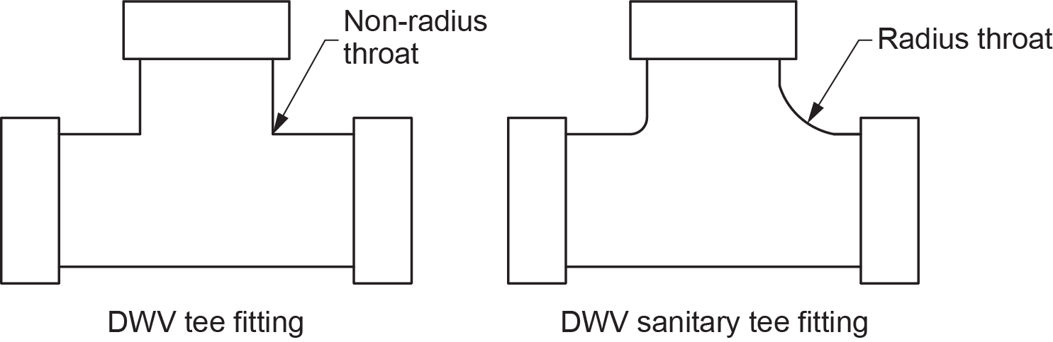
Tee and Cross Fittings
These fittings are not the sanitary tee fittings you are probably familiar with. These fittings do not have a radius throat on the fitting branch to change flow direction from horizontal to vertical (Figure 1).
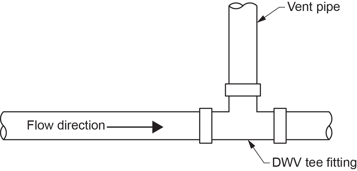
The NPC requires the following:
- A tee fitting shall not be used in a drainage system, except to connect a vent pipe (Figure 2).
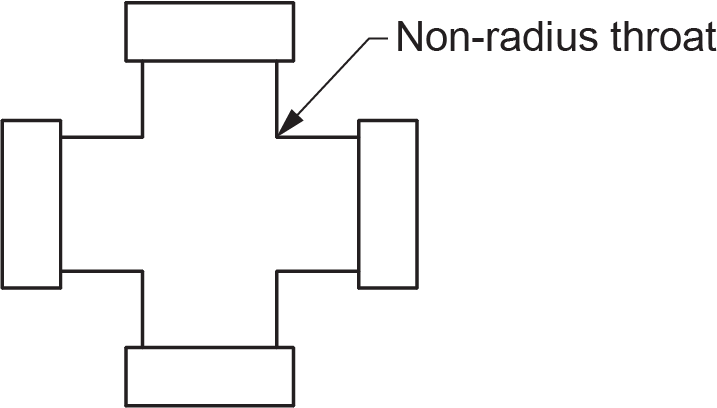
- A cross fitting shall not be used in a drainage system (Figure 3).
Sanitary Tee Fittings
This fitting is often misused in a DWV system. Its proper use is to connect a horizontal branch or fixture drain to a nominally vertical branch or stack. The only time this fitting can be used in a horizontal drain pipe is to connect a nominally vertical dry vent to the system. Using a sanitary tee to change flow direction through its branch inlet from vertical to horizontal or to connect drainage pipes in the horizontal plane is never allowed.
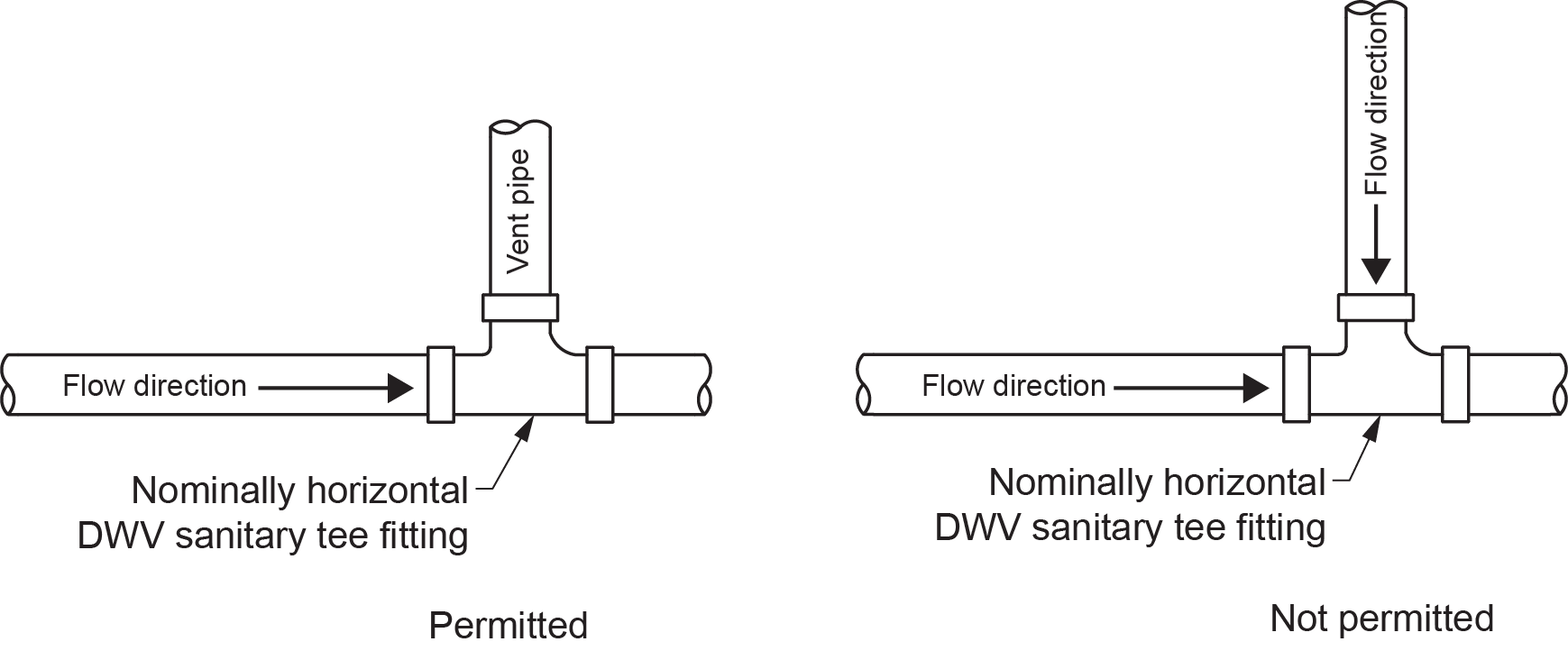
The NPC requires that:
- A single or double sanitary tee fitting shall not be used in a nominally horizontal sanitary drainage pipe, except that a single sanitary tee fitting may be used to connect a vent pipe (Figure 4).
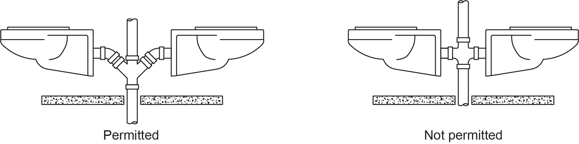
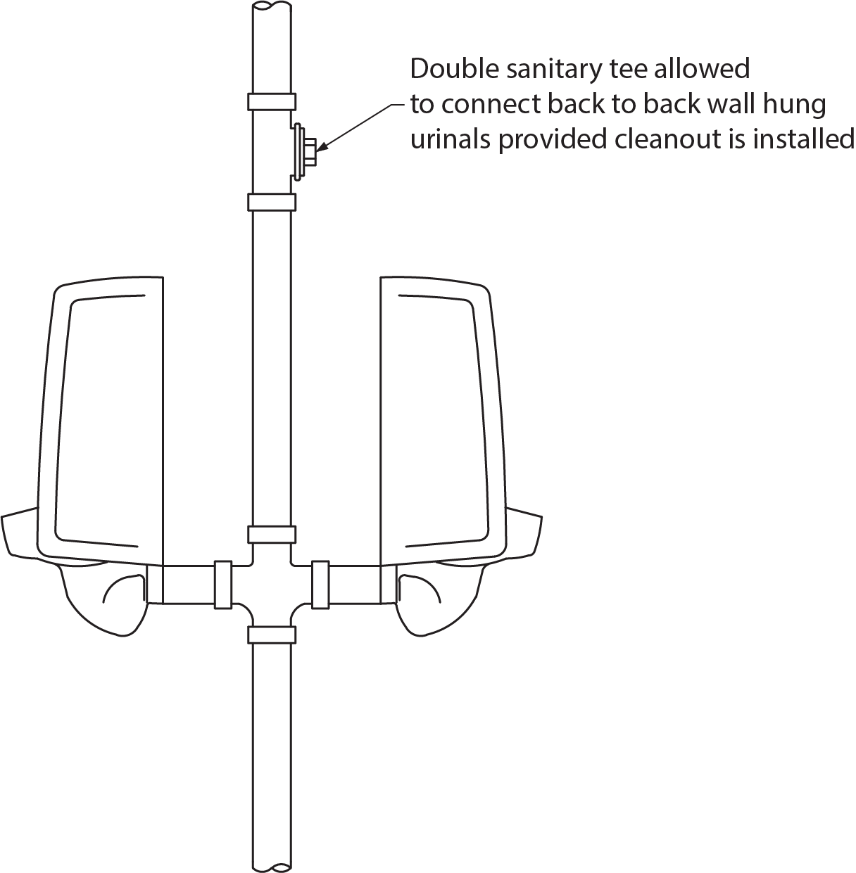
- A double sanitary tee fitting cannot be used to connect the trap arms of back outlet water closets installed back-to-back (Figure 5) or two urinals with no cleanout fitting provided above the connection (Figure 6). Using a double wye fitting and 45° elbow combination is acceptable.
90° Elbows
These fittings are also called bends, which helps distinguish these DWV fittings from other 90° elbows that may be used in a pressurized system. Bends are described by the fraction of a circle that they sweep. A [latex]\tfrac{1}{4}[/latex] bend changes direction 90° ([latex]\tfrac{1}{4}[/latex] of 360°), a [latex]\tfrac{1}{8}[/latex] bend changes direction 45°, and so on. Bends may change flow in any direction, except for [latex]\tfrac{1}{4}[/latex] bends, which have some restrictions.
90° elbows (quarter bends) come in regular (short-radius) and long-radius styles. A long-radius bend is one whose centreline radius is at least equal to the diameter of the bend. Using long-radius bends to join two sanitary drainage pipes is unrestricted.
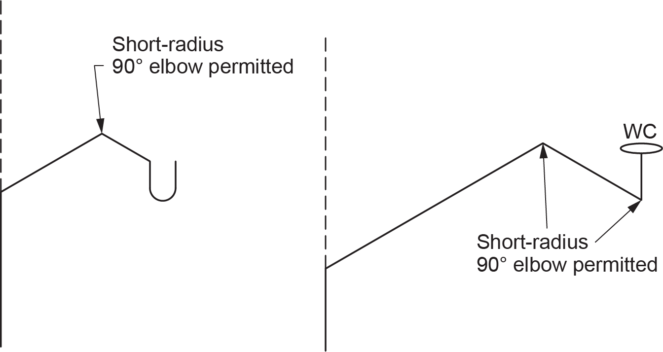
Short-radius bends used in systems of 100 mm (4 in.) in size or less are only permitted to do the following:
- Change flow direction from horizontal to vertical in the direction of flow or where a trap arm enters a wall (Figure 7)
- Connect trap arms — such as trap arms of water closets — s-trap standards, or any other fixture that also discharges vertically and depends on siphonic action to function properly
Installing Fixtures and Associated Equipment
All plumbing fixtures shall not be installed in a room without lighting and ventilation. Every fixture, appliance, interceptor, cleanout, valve, device, or piece of equipment shall be located so that it is readily accessible for use, cleaning, and maintenance.
Additionally, there are a number of requirements specific to the type of fixture.
Showers
- Every shower receptor shall be constructed and arranged so that water cannot leak through the walls or floor.
- A single shower drain shall serve not more than six showerheads.
- Where a shower drain serves two or more showerheads, the floor shall be sloped and the drain located so that water from one head cannot flow over the area that serves another head.
- Except for column showers, when a battery of showerheads is installed, the horizontal distance between two adjacent showerheads shall be not less than 750 mm (30 in.).
Water Closets
- When a water closet is installed in a washroom for public use, it shall be of the elongated type and be provided with a seat of the open front type.
- When installing a water closet, the NPC requires that every screw, bolt, nut, and washer shall be of corrosion-resistant materials when used to:
- Connect a water closet to a water closet flange
- Anchor the water closet flange to the floor
- Anchor the water closet to the floor
Clothes Washer
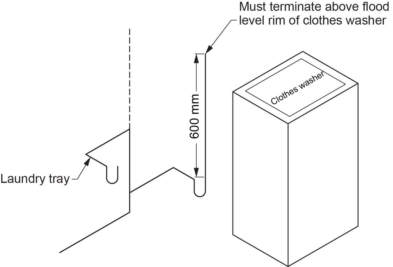
- Where clothes washers do not drain to a laundry tray, the trap inlet shall be fitted with a vertical standpipe not less than 600 mm (24 in.) long (measured from the trap weir) that terminates above the flood level rim of the clothes washer (Figure 8).
Sumps or Tanks
- Piping that is too low to drain into a building sewer by gravity shall be drained to a sump or receiving tank.
- Where the sump or tank receives sewage, it shall be watertight, airtight, and vented.
- Equipment such as a pump or ejector that can lift the contents of the sump or tank and discharge it into the building drain or building sewer shall be installed.
- Where the equipment does not operate automatically, the capacity of the sump shall be sufficient to hold at least a 24-hour accumulation of liquid.
- Where there is a building trap, the discharge pipe from the equipment shall be connected to the building drain downstream of the trap.
- The discharge pipe from every pumped sump shall be equipped with a union, a check valve, and a shutoff valve installed, in that sequence, in the direction of discharge.
- The discharge piping from a pump or ejector shall be sized for optimum flow velocities at pump design conditions.
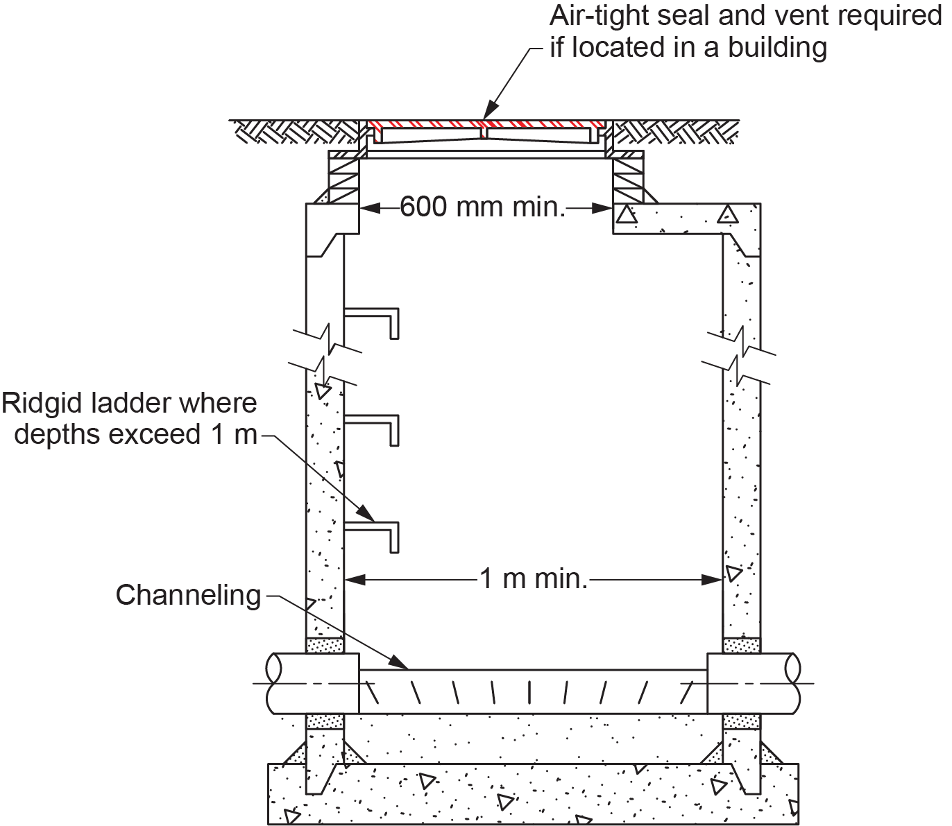
Manholes
- A manhole, including the cover, shall be designed to support all loads imposed upon it.
- A manhole shall be provided with the following (Figure 9):
- A cover that provides an airtight seal, if located within a building
- A rigid ladder of a corrosion-resistant material where the depth exceeds 1 m (39 in.)
- A vent to the exterior, if located within a building
- A manhole shall have a minimum horizontal dimension of 1 m (39 in.), except that the top 1.5 m (60 in.) may be tapered from 1 m down to a minimum of 600 mm (24 in.).
- A manhole in a sanitary drainage system shall be channeled to direct the flow of effluent.
Mobile Home Sewer Service
A building sewer intended to serve a mobile home shall be not less than 100 mm (4 in.) in size, terminated above ground, and provided with the following:
-
- A tamperproof terminal connection capable of being repeatedly connected, disconnected, and sealed
- A protective concrete pad
- A means to protect it from frost heave
Protection from Backflow in Drainage Systems
The NPC allows a backwater valve to be installed in a building drain provided that it is of a “normally open” design and does not serve more than one dwelling unit. As an alternative, where a building drain or a branch may be subject to backflow, a gate valve or backwater valve shall be installed on every fixture drain connected to it when the fixture is located below the level of the adjoining street. If more than one fixture is located on a storey and all are connected to the same branch, the gate valve or backwater valve may be installed on the branch. If the alternative method is used and the fixture is a floor drain, a removable screw cap may be installed on the upstream side of the trap.
A subsoil drainage pipe that drains into a sanitary drainage system subject to surcharge shall be connected in such a manner that sewage cannot back up into the subsoil drainage pipe.
Prohibitions
Fixtures
- A dishwashing sink and a food preparation sink shall not have concealed overflows.
Connection to Public Services
- Piping in any building connected to public services shall be connected separately from the piping of any other building, except that an ancillary building on the same property may be served by the same service.
Restrictions
Fixture Locations
- Urinals shall not be installed adjacent to wall and floor surfaces that are pervious to water.
- Indirect connections or any trap that may overflow shall not be located in a crawl space or any other unfrequented area.
- Except for an organic solids interceptor, equipment discharging waste with organic solids shall not be located upstream of a grease interceptor.
- A floor drain or other fixture located in an oil transformer vault, a high-voltage room, or any room where flammable, dangerous, or toxic chemicals are stored or handled shall not be connected to a drainage system.
- A macerating toilet system shall only be installed where no connection to a gravity sanitary drainage system is available.
- Where a drain is provided in an elevator pit, it shall be connected directly to a sump located outside the elevator pit, and the drain pipe that connects the sump to the drainage system shall have a backwater valve.
Connections to the Drainage System
- A saddle hub or fitting shall not be installed in a DWV system.
- The NPC does not allow a fixture to be connected to a lead bend or stub serving a water closet.
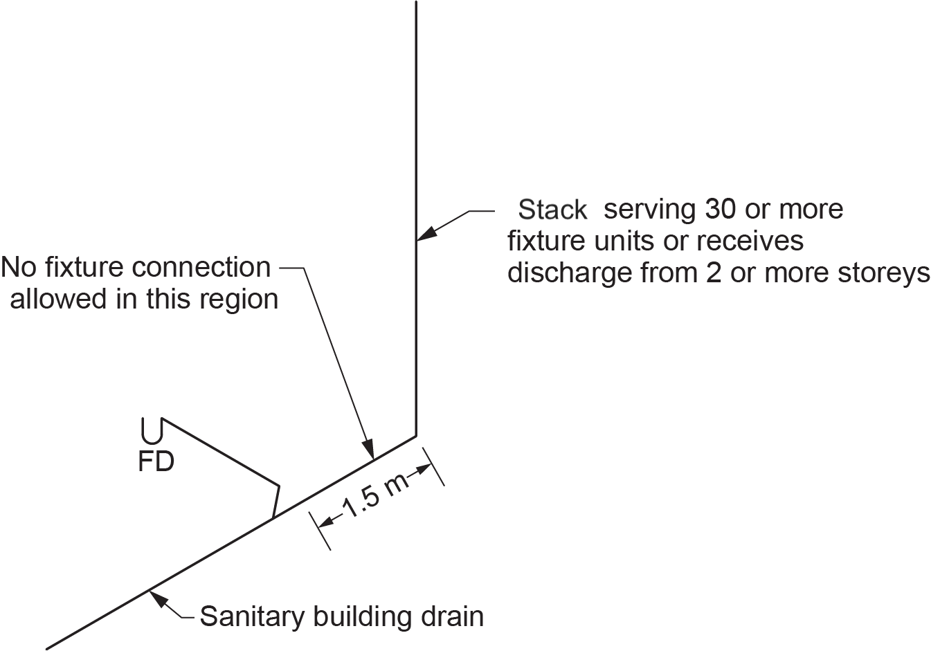
- The connection of a sanitary drainage pipe to a nominally horizontal sanitary drainage pipe or a nominally horizontal offset in a stack shall be not less than 1.5 m (60 in.) measured horizontally from the bottom of a stack or the bottom of the upper vertical section of the stack that:
- Receives a discharge from 30 or more fixture units
- Receives a discharge from fixtures located on two or more storeys (Figure 10)
- Fixtures shall be directly connected to a sanitary drainage system, with the exception of a drinking fountain, which may be indirectly connected to a drainage system.
The following devices must be indirectly connected to a drainage system:
-
- Device for displaying, storing, preparing, or processing food or drink
- Sterilizer
- Device that uses water as a cooling or heating medium
- Water-operated device
- Water treatment device
- Drain or overflow from a water system or a heating system
For the fixtures listed above, the following methods of directly connecting to a shared drain pipe may also be used, as they will give the same level of protection as an indirect individual fixture connection.
- In reference to all of the above fixtures, two or more fixture outlet pipes that serve outlets from a single fixture may be directly connected to a branch that:
- Has a size of not less than 32 mm (1.25 in.)
- Is terminated above the flood level rim of a directly connected fixture to form an air break
- The above fixtures listed in A and B may be directly connected to a pipe that:
- Is terminated to form an air break above the flood level rim of a fixture directly connected to a sanitary drainage system
- Is extended through the roof when fixtures on three or more storeys are connected to it
- The above-fixtures listed in Items C through E may be directly connected to a pipe that:
- Is terminated to form an air break above the flood level rim of a fixture directly connected to a storm drainage system
- Is extended through the roof when fixtures on three or more storeys are connected to it
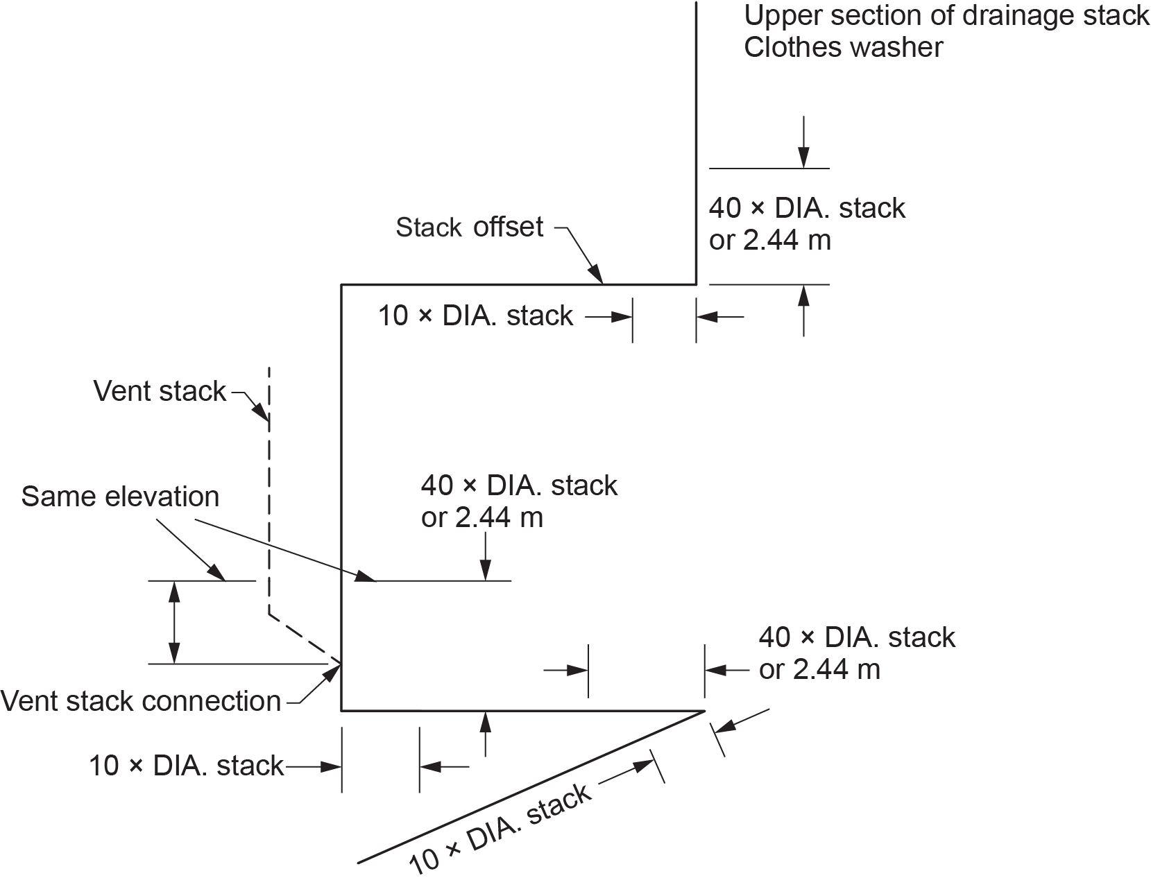
Suds Pressure Zones
Detergents that produce high volumes of suds in clothes washers have created a serious problem called suds pressure in all residential occupancy buildings and more notably in high-rise buildings. Whenever a sanitary drainage pipe receives waste from two or more clothes washers, the drainage and vent piping below the clothes washer connections must be arranged to avoid connecting to any zone where suds pressure exists.
High suds pressure zones occur at every change in direction — vertically or horizontally — greater than 45°. Because liquid discharge is heavier than suds, it easily flows through the suds-loaded drainage piping without carrying the suds along with it, leaving the most of the suds behind. The air and liquid flowing in the drainage pipe compresses the suds and forces them to move through any available path of relief, such as the building drain, any branches connected to the building drain, the vent stack, branch vents, individual vents, or combinations of these. Excessively high suds pressures are capable of blowing out the seals of traps, with suds also appearing in fixtures.
The NPC restricts the connection of sanitary drainage pipes to suds pressure zones within certain distances, as listed below:
- 40 times the size of the sanitary drainage pipe or 2.44 m (96 in.) maximum vertical, whichever is less, before changing direction (Figure 11)
- 10 times the size of the nominally horizontal sanitary drainage pipe after changing direction
- Where a vent pipe is connected into the suds pressure zone, no other vent pipe shall be connected to that vent pipe within the height of the suds pressure zone.
High-Temperature Wastes
High-temperature wastes (above 75°C/167°F) must never discharge directly into the drainage system. High temperatures can cause piping to expand and contract excessively, resulting in harmful effects. Joints may be pulled apart or loosened, and solidly bedded pipe may be broken. The discharges from boiler blow-offs, steam exhaust, condensate, and so on must be cooled down to at least 75°C before connecting to the drainage system. This may be accomplished by piping the high-temperature discharge to a water-supplied sump or a cooling tank.
Acidic or Corrosive Wastes
All acidic or corrosive waste requires neutralization before being permitted to be discharged into any public sewer for disposal. The primary procedures used most often are:
- Dilution
- Direct continuous contact with limestone chips in an acid-neutralizing basin
- Continuous or batch treatment in an automated neutralization system using chemical feed neutralizing
The connection of the neutralizing basin to the sanitary drainage system shall be indirect or through a trap.
Sanitary Drainage Pipes Locations
To prevent contamination of potable water or food sources in the event of a DWV system leak, the NPC requires that a sanitary drainage pipe not be located directly above the following:
- Non-pressure potable water storage tanks
- Manholes in pressure potable water storage tanks
- Food-handling or food-processing equipment
Traps and Interceptors
Traps
The NPC (2020) places restrictions on how a p-trap is used and manufactured. The following are some of those limitations, restrictions, and clarifications:
- Every trap shall have a trap seal depth of not less than 38 mm (1.5 in.). For fixtures draining to an acid waste system, the trap seal depth shall be a minimum of 50 mm (2 in.).
- Traps shall be manufactured with single walls so that a failure of the trap seal wall will cause exterior leakage.
- Traps shall have a non-mechanical water seal so that it does not depend on the action of moving parts to be effective.
- Every trap that serves a lavatory, sink, or laundry tray shall be provided with a cleanout plug located at the lowest point of the trap. The cleanout plug shall be of the same material as the trap. The one exception to this requirement concerns a cast-iron trap, which must have a brass cleanout plug to facilitate removal. If a cleanout plug is not provided, then the trap shall be designed so that part or all of the trap can be removed for cleaning purposes.
- A drum trap shall not be used as a fixture trap unless required to serve as an interceptor and access for servicing is provided.
- A tubular trap shall be used only in accessible locations. A tubular trap is made of thin-walled material and is not of the thickness of DWV; therefore, it cannot be concealed.
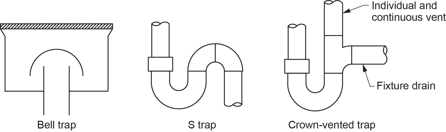
Prohibited Traps
As mentioned, the NPC (2020) places restrictions on how a p-trap is used and manufactured. The following are some of those limitations, restrictions, and clarifications:
- Bell trap: were sometimes used in floor drains installed many years ago (Figure 12). Their installation is prohibited by the NPC.
- S-trap: was very common years ago when most plumbing drains came up through the floor instead of out from a wall, but they are subject to losing their trap seal through self-siphoning. Except for an s-trap standard, the s-trap shown in Figure 12 is prohibited by Clause 2.5.6.3.(1)(b), which limits the maximum fall on a trap arm fixture drain to not more than the inside diameter of the pipe.
- Crown vented trap: has a vent rising from the top of the trap and is prohibited by Clause 2.5.6.3.(1)(a), which requires that the distance from the trap weir to the vent be not less than twice the size of the fixture drain.
Sanitary Drainage System Traps
The NPC requires that every fixture shall be protected by a separate trap, with certain exceptions:
- One trap may protect all the trays or compartments of a two- or three-compartment sink, a two-compartment laundry tray, or two similar single-compartment fixtures located in the same room.
- One trap may serve a group of floor drains, shower drains, washing machines, or laboratory sinks if the fixtures are in the same room and not located where they can receive food or other organic matter.
- An indirectly connected fixture that can discharge only clear-water waste, other than a drinking fountain, need not be protected by a trap.
- Where a domestic dishwashing machine equipped with a drainage pump discharges through a direct connection into the fixture outlet pipe of an adjacent kitchen sink or disposal unit, the pump discharge line shall rise as high as possible to just under the counter and connect on the inlet side of the sink trap by means of a wye fitting or to the disposal unit.
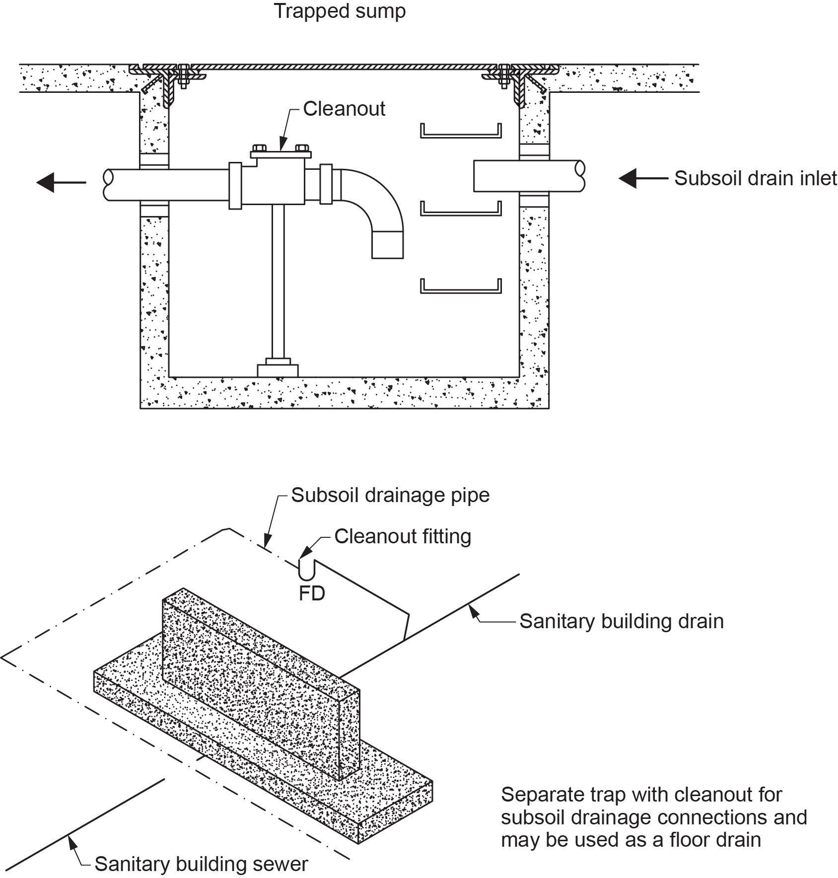
Traps Used for Subsoil Drainage Pipes Connecting to a Sanitary Drainage System
The NPC requires that, when a subsoil drainage pipe is connected to a sanitary drainage system (Figure 13), a trap must be installed between the subsoil drainage pipe and the sanitary drainage system. The connection shall be made on the upstream side of the trap with a cleanout fitting. An alternative to this arrangement could be through the use of a trapped sump.
Trap Seals
When a floor drain trap seal is lost, objectionable smells and gases may enter the building. Therefore, the water seal in floor drain traps must be maintained under all circumstances. The NPC requires that provision shall be made for maintaining the trap seal of a floor drain by using:
- A trap seal primer
- The drain as a receptacle for an indirectly connected drinking fountain
- Some other equally effective means
Interceptors
Interceptors are required when conditions provide an opportunity for harmful or unwanted materials to enter a sanitary drainage system. When oil, grease, sand, or other harmful substances are likely to enter a drainage system, an interceptor is required. The NPC has a number of regulations regarding interceptors used in drainage systems:
- An interceptor may serve as a trap, provided that it has an effective water seal of not less than 38 mm ([latex]1\tfrac{1}{2}[/latex] in.).
- Every interceptor shall be designed so that it can be readily cleaned.
- Every interceptor shall have sufficient capacity to perform the service for which it is provided.
Grease Interceptor
- Where a fixture discharges sewage that includes fats, oils, or grease and is located in a public kitchen, restaurant, or care or detention occupancy, it shall discharge through a grease interceptor.
- A grease interceptor shall be designed so that it does not become air bound (flow stoppage due to trapped air), and does not have a water jacket.
Oil Interceptor
- Where the discharge from a fixture may contain oil or gasoline, an oil interceptor shall be installed.
Solid Interceptor
- Where a fixture discharges sand, grit, or similar materials, an interceptor designed for the purpose of trapping such discharges shall be installed.
Cleanouts
Cleanouts are a means of accessing the interior of drainage pipes. They are needed so that blockages in drains may be cleared. Without cleanouts, it is much more difficult to clean the drain. The NPC has established minimums for the size of cleanouts and their placement in the drainage system.
Cleanouts for Drainage Systems
The NPC requires that:
- Every plug, cap, nut, or bolt intended to be removable from a ferrous fitting shall be of a non-ferrous material.
- A cleanout fitting that, as a result of normal maintenance operations, cannot withstand the physical stresses of removal and reinstallation or cannot ensure a gas-tight seal shall not be installed.
- Every sanitary drainage system shall be provided with cleanouts that will permit cleaning of the entire system through “one-way rodding” in the direction of flow or “two-way rodding” in either direction originating at the cleanout.
- Cleanouts and access covers shall be located so that their openings are readily accessible for drain cleaning purposes.
- A cleanout shall not be located in a floor assembly in a manner that may constitute a hazard or allow it to be used as a floor drain.
- Cleanouts that allow rodding in only one direction shall be installed to permit rodding in the direction of flow.
- There shall be no change of direction between a cleanout fitting and the trap that it serves.
- The piping between a cleanout fitting and the drainage piping or vent piping that it serves shall not change direction by more than 45°.
- Cleanouts shall be installed so that the cumulative change in direction is not more than 90° between cleanouts in a drip pipe from a food receptacle or in a fixture drain serving a kitchen sink.
Required Locations
- A cleanout fitting shall be provided on the upstream side and directly over every running trap.
- Where a running trap serves a building trap, it shall be provided with a cleanout fitting on the upstream side of and directly over the trap, be located upstream of the building cleanout, and be located inside the building as close as practical to the place where the building drain leaves the building or outside the building in a manhole.
- Every building drain shall be provided with a cleanout fitting located as close as practical to the place where the building drain leaves the building.
- Every stack shall be provided with a cleanout fitting at the bottom of the stack, not more than 3 m (9 ft 10 in.) upstream of the bottom of the stack, or on a wye fitting connecting the stack to the building drain or branch.
- A cleanout shall be provided to permit the cleaning of the piping downstream of an interceptor.
- Cleanouts serving fixtures in health care facilities, mortuaries, laboratories, and similar occupancies where contamination by body fluids is likely shall be located a minimum of 150 mm (6 in.) above the flood level rim of the fixture.
Minimum Size and Maximum Spacing
- Cleanouts are required to be the same size as the pipe they are serving unless the pipe is larger than 100 mm (4 in.). The maximum spacing between cleanouts depends on whether or not they provide one- or two-way rodding, as explained in Table 2.4.7.2. (NPC, 2020, B 2-29; refer to Table 2 below).
- Cleanouts for building drains shall be a minimum of 4 in. (100 mm) in size.
| Size of Drainage Pipe (m) | Minimum Size of Cleanout (in.) | Maximum Spacing — One-way Rodding (m) | Maximum Spacing — Two-way Rodding (m) |
|---|---|---|---|
| Less than 3 | Same size as drainage pipe | 7.5 | 15 |
| 3 and 4 | 3 | 15 | 30 |
| Over 4 | 4 | 26 | 52 |
Regulations for Cleanouts Serving Building Sewers
- Where a cleanout is required on a building sewer 200 mm (8 in.) or larger in size, it shall be a manhole.
- A building sewer shall not change direction or slope between the building and public sewer or between cleanouts, except that pipes not more than 150 mm (6 in.) in size may change direction by not more than 5° every 3 m (9 ft 10 in.) or by using fittings with a cumulative change in direction of not more than 45°.
- Where a building sewer connects to another building sewer other than by a manhole, the developed length between the building and the building sewer to which it connects shall not exceed 30 m (98 ft 5 in.).
- The developed length of a building sewer between the building and the first manhole to which the building sewer connects shall not exceed 75 m (246 ft).
- The spacing between manholes serving a building sewer 600 mm (24 in.) or less in size shall not exceed 90 m (295 ft) and over 600 mm in size shall not exceed 150 m (490 ft).
Venting
Vent Pipe Drainage
When venting systems are installed, the vents should have a small amount of grade in the downstream direction to allow condensation to drain. Vents cannot be installed in a trapped position; this will fill the vent up with condensation and close it off. Unless it is impractical to do so, vents are required to be installed in a nominally vertical position, which will allow the condensation to flow to the drainage system and keep the venting system free-flowing.
The NPC requires that every vent pipe shall be installed without any depressions in which moisture can collect.
Vent Pipe Locations on Trap Arms
- Except for a wet vent, every vent pipe extends above the flood level rim of every fixture that it serves before turning nominally horizontal or being connected to another vent pipe.
- No vent pipe shall be connected in such a manner that a blockage in a sanitary drainage pipe would cause waste to drain through the vent pipe to the drainage system.
- When a vent pipe, other than a wet vent, is connected to a nominally horizontal sanitary drainage pipe, the connection shall be above the horizontal centreline of the sanitary drainage pipe.
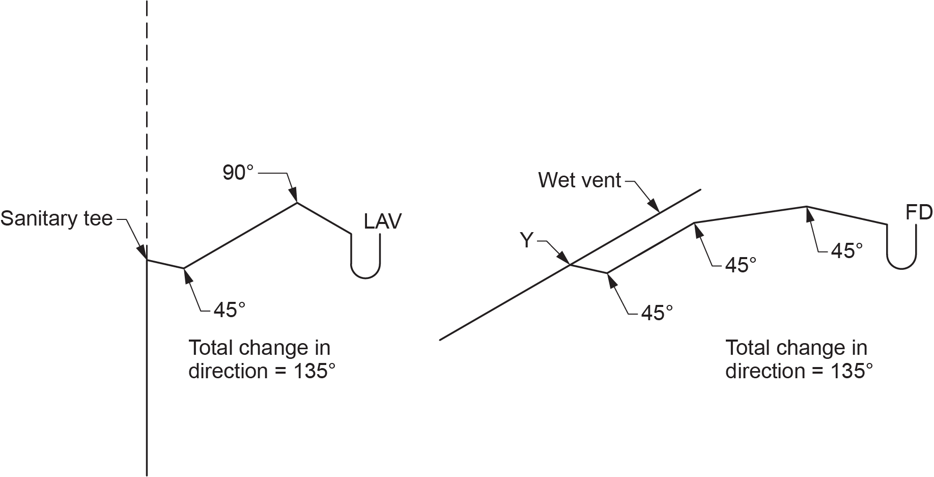
- Except for water closets, s-trap standards, or any other fixture that depends on siphonic action to function properly, a vent pipe that protects a fixture trap shall be located so that:
- The developed length of the trap arm is not less than twice the size of the fixture drain
- The total fall of the trap arm does not exceed its size
- The trap arm does not have a cumulative change in direction of more than 135° (Figure 14)
The maximum length of a trap arm upstream of the vent connection shall not exceed the distances shown in Table 2.5.6.3. (Table 3) based on trap size:
| Trap Size Served (in.) | Maximum Trap Arm Length (m) | Minimum Slope |
|---|---|---|
| 1.25 | 1.5 | [latex]\tfrac{1}{50}[/latex] |
| 1.50 | 1.8 | [latex]\tfrac{1}{50}[/latex] |
| 2 | 2.4 | [latex]\tfrac{1}{50}[/latex] |
| 3 | 3.6 | [latex]\tfrac{1}{50}[/latex] |
| 4 | 9.8 | [latex]\tfrac{1}{100}[/latex] |
Vent Pipe Locations on Trap Arms Serving Fixtures that Depend on Siphonic Action
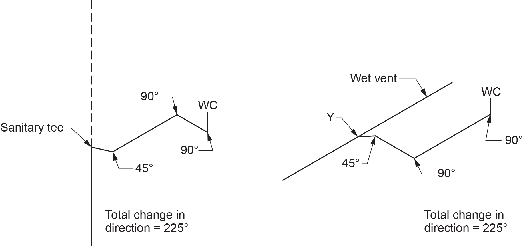
The trap arm of water closets, s-trap standards, and any other fixture that also discharges vertically and depends on siphonic action to function properly shall not have a cumulative change in direction of more than 225° (Figure 15).
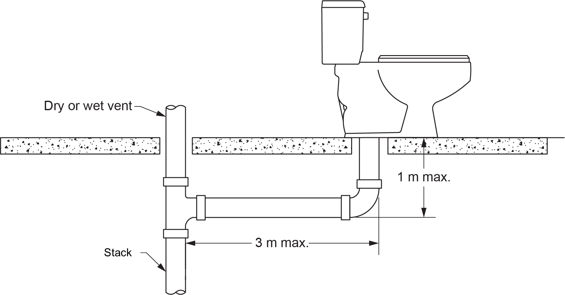
A vent pipe that protects a water closet or any other fixture that also depends on siphonic action to function properly shall be located so that the distance between the connections of the fixture drain to the fixture and the vent pipe does not exceed:
- 1 m (39 in.) in the vertical plane
- 3 m (9 ft 10 in.) in the horizontal plane (Figure 16)
Island Venting
With the acceptance of air admittance valves by the NPC, many island installations are being installed using this device. It is strongly suggested that this device only be used if the piping configurations shown in Figure 17 is not possible. Air admittance valves are a one-way check valve and, as such, do not allow free flow of air through the system. As well, they are a mechanical device that can and do fail, requiring replacement. Unfortunately, the NPC does not give much guidance to the installer with regard to this practice. In the “Notes to Part 2” section of the code, A.2.4.8.2.(1) illustrates two installations that limit the length of the fixture outlet pipe and the length of the trap arm in relation to the trap size (Figure 17).
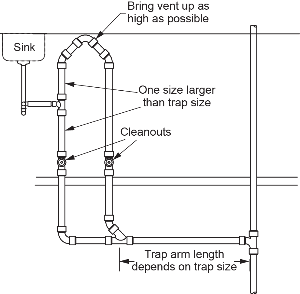
If the vent riser is further away from the fixture than permitted in Figure 17, some jurisdictions allow an alternative piping arrangement that uses a “foot vent” running below the floor, where there is no restriction to length (Figure 18).
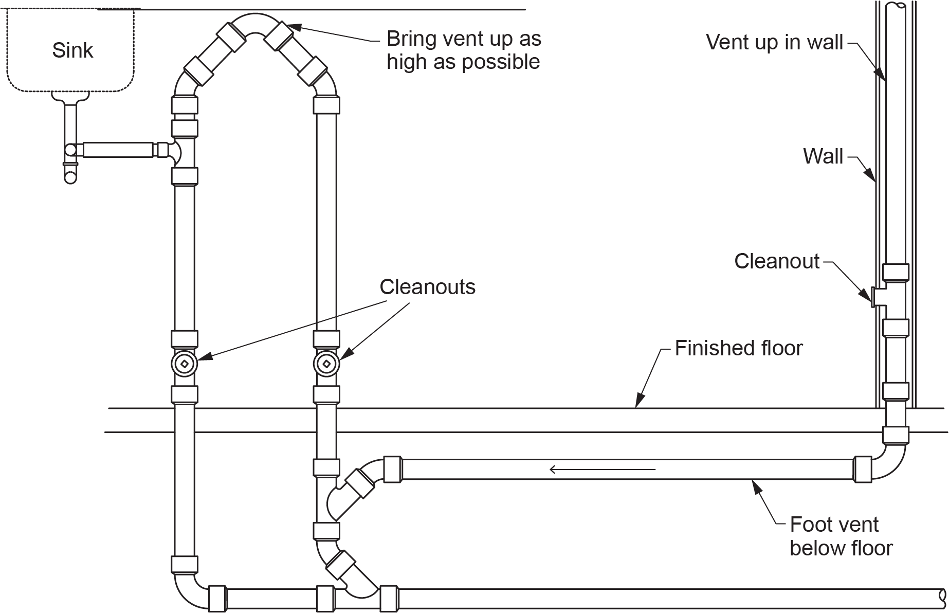

Always get approval from your local plumbing inspector before installing this type of vent.
Air Admittance Valves
Air admittance valves are not a replacement for the venting system but are only an added component of an existing sanitary system. This means that this type of valve is not intended to replace a vent extending to open air nor will it help circulate air as needed for relief vents or circuit vents. The valve will open only when a negative pressure or a pressure below atmospheric is present in the drainage system. It remains closed when subjected to a positive pressure.
Using air admittance valves is limited because the valve shall only be used under certain conditions and after the AHJ has determined it is warranted.
[Air admittance valves] shall only be used to vent:
- Fixtures located in island counters
- Fixtures that may be affected by frost closure of the vent due to local climatic conditions
- Fixtures in one- and two-family dwellings undergoing renovation
- Installations where connection to a vent may not be practical
[Air admittance valves] shall be located:
- Not less than 100 mm (4 in.) above the fixture drain served
- Within the maximum developed length permitted for the vent
- Not less than 150 mm (6 in.) above insulation materials
Installation Requirements
- Shall not be installed in supply or return air plenums or in locations where they may be exposed to freezing temperatures
- Shall be installed in accordance with the manufacturer’s installation instructions
- Shall be rated for the size of vent pipe to which they are connected
- Shall be accessible and located in a space that allows air to enter the valve
Future Connections
- Where provision is made for a fixture to be installed in the future, the drainage system and venting system shall be sized accordingly, and provision shall be made for the necessary future connections.
- Except in a situation where a sewage sump is installed that requires a minimum 50 mm (2 in.) vent, every storey in which plumbing is or may be installed, including the basement of a single-family dwelling, shall have a vent pipe of at least 38 mm ([latex]1\tfrac{1}{2}[/latex] in.) in size extending into or passing through it for the provision of future connections.
- Unused vent pipes installed for future connections shall be permanently capped with an end cleanout or an adapter and plug.
Miscellaneous Vent Pipes
Venting Requirements for Corrosive Waste Piping or Dilution Tanks
Venting systems for drain piping or dilution tanks conveying corrosive waste shall extend independently and terminate in outside air.
The minimum size requirement for the vent pipe serving a dilution tank is identical to that serving a sewage sump. It is allowed to be one size smaller than the size of the largest branch or fixture drain draining to the tank but cannot be less than 50 mm (2 in.) nor does it need to be greater than 100 mm (4 in.).
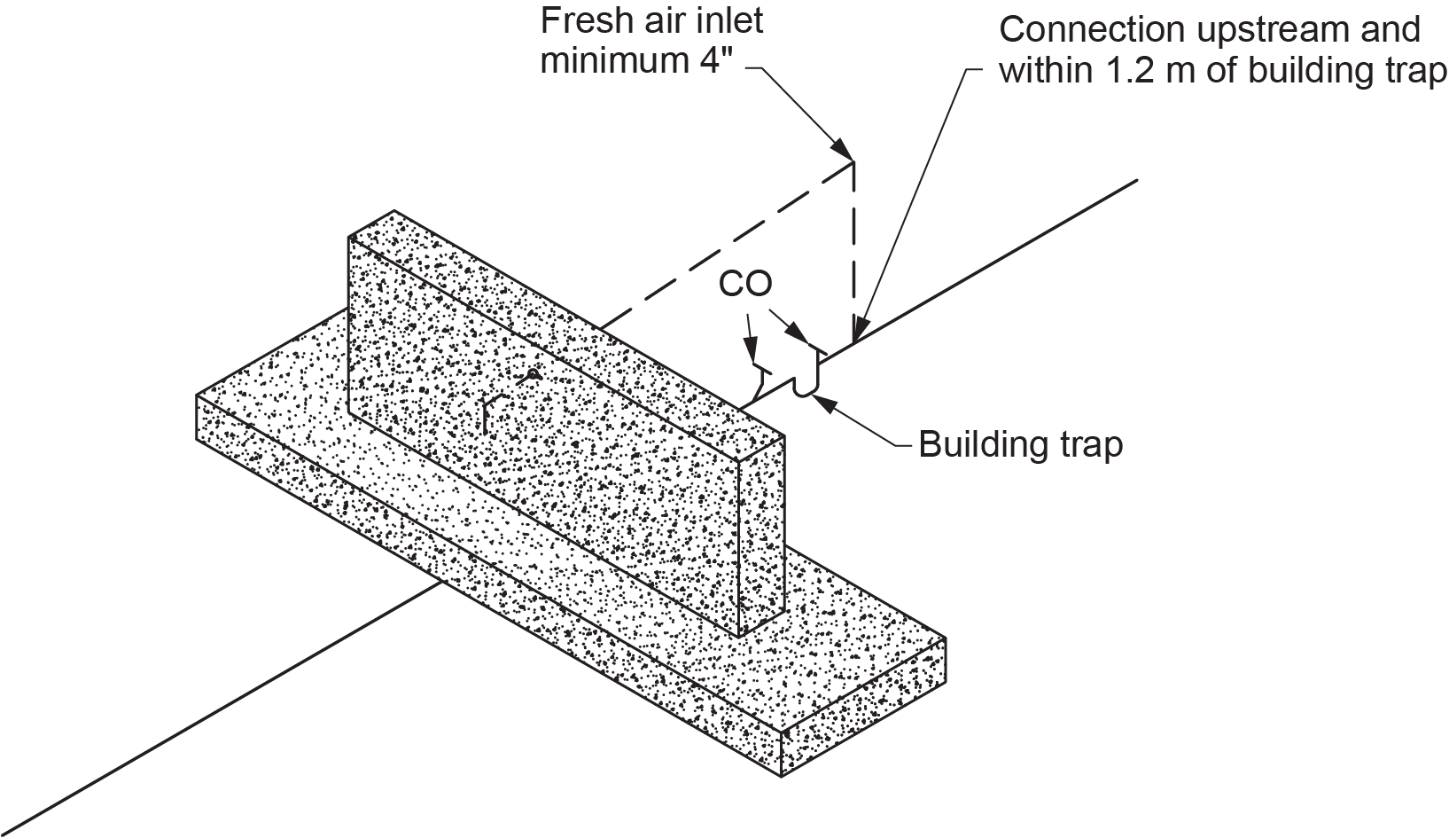
Fresh Air Inlets Serving Building Traps
A fresh air inlet not less than 100 mm (4 in.) in size shall be connected upstream and within 1.2 m (47 in.) of the building trap and downstream of any other connection (Figure 19).
Venting Requirements for Manholes Installed Inside a Building
The minimum size of a vent pipe that serves a manhole within a building shall be 50 mm (2 in.).
Venting Requirements for Oil and Grease Interceptors
In some instances, grease interceptors and, more often, oil interceptors are installed outside of the building structure. In this case, it is important to note that every vent pipe that serves an oil or grease interceptor located outside a building shall be not less than 75 mm (3 in.) in size in areas where it may be subject to frost closure.
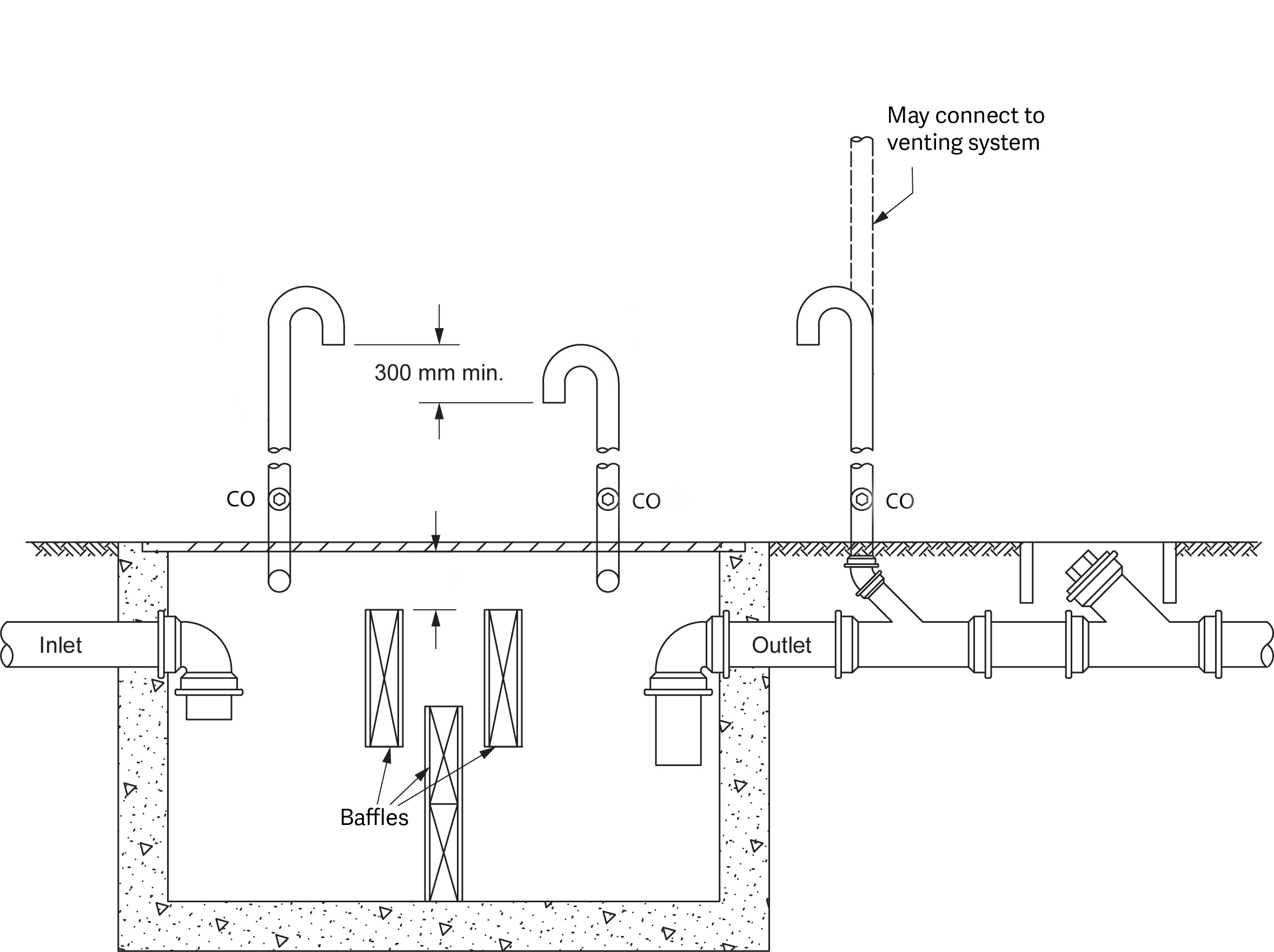
An oil interceptor functions in the same way as a grease interceptor except that flammable fumes must be expelled using natural air currents. This is done by connecting the top area of adjacent compartments to allow air flow up through to individual “fume” vents that extend to open air. A vent is required on the outlet of the interceptors to prevent siphoning of the interceptor.
National Plumbing Code Requirements for Oil and Grease Interceptors
- Every oil interceptor shall be provided with two vent pipes that:
- Connect to the interceptor at opposite ends
- Do not connect to each other or any other vent pipe and extend independently to open air
- Terminate not less than 2 m ([latex]78\tfrac{3}{4}[/latex] in.) above ground and at elevations differing by at least 300 mm (12 in.)
- The vent pipes are permitted to be one size smaller than the largest connected drainage pipe but not less than 32 mm (1.25 in.) in size or can be sized in accordance with the manufacturer’s recommendations.
- Adjacent compartments within every oil interceptor shall be connected to each other by a vent opening (Figure 20).
- Where a secondary receiver for oil is installed in conjunction with an oil interceptor, it shall be vented in accordance with the manufacturer’s recommendations, and the vent pipe shall:
- In no case be less than 38 mm (1.25 in.) in size
- Extend independently to outside air
- Terminate not less than 2 m ([latex]78\tfrac{3}{4}[/latex] in.) above ground
Vent Terminals
Vent terminals are fresh air inlets serving a building trap or vents serving an oil interceptor and must extend above the roof level. The proximity of the vent terminal location to windows, doors, or other ventilating openings must be considered.
National Plumbing Code Requirements for Vent Terminals
- The vent terminal should be located:
- Not less than 1 m (39 in.) above or not less than 3.5 m (138 in.) in any other direction from every air inlet, openable window, or door
- Not less than 2 m (47 in.) above or not less than 3.5 m in any other direction from a roof that supports an occupancy
- Not less than 2 m above ground
- Not less than 1.8 m (72 in.) from every properly line
- The vent terminal should be:
- Terminated high enough to prevent the entry of roof drainage but not less than 150 mm (6 in.) above the roof or above the surface of storm water that could pond on the roof
- Provided with flashing to prevent the entry of water between the vent pipe and the roof
- Supported or braced if a vent pipe that may be subject to misalignment terminates above the surface of a roof
- The vent terminal shall be protected from frost closure by:
- Increasing its diameter at least one size, but not less than 75 mm (3 in.) in size, immediately before it penetrates the roof
- Insulating the pipe
- Protecting it in some other manner
- Under certain conditions, a vent pipe is allowed to be installed outside a building, provided that the following conditions are met:
- No single change in direction of the vent pipe exceeds 45°.
- All parts of the vent pipe are nominally vertical.
- In areas where the vent pipe may be subject to frost closure, it is increased to not less than 75 mm (3 in.) in size before penetrating a wall or roof.
- Where the building is four storeys or less in height, the vent pipe terminates above the roof of the building.
Vent Pipe Flashing
Flashing fabricated on site for vent pipes shall be fabricated from one of the following:
- Copper sheet: not less than 0.33 mm (0.013 in.) thick
- Aluminum sheet: not less than 0.48 mm (0.0189 in.) thick
- Alloyed zinc sheet: not less than 0.35 mm (0.0138 in.) thick
- Lead sheet: not less than 1.73 mm (0.068 in.) thick
- Galvanized steel sheet: not less than 0.33 mm (0.013 in.) thick
- Polychloroprene (neoprene): not less than 2.89 mm (0.114 in.) thick
Hangers and Supports
The method of supporting pipes is regulated by the NPC. There are requirements for the type of materials you may use and how you may use them.
The hangers used to support pipe must be capable of supporting the pipe and its contents at all times. The hanger must be attached to the pipe and to the structural member holding the hanger in a satisfactory manner to maintain alignment. Where a hanger is attached to concrete or masonry, it shall be fastened by metal or expansion-type plugs inserted or built into the concrete or masonry.
Piping, fixtures, tanks, or devices shall be supported independently of each other, and every water-closet bowl shall be securely attached to the floor or wall by means of a flange and shall be stable. Wall-mounted fixtures shall be independently supported so that no strain is transmitted to the piping.
The hangers used must be compatible with the pipe they are supporting. You must use a hanger that will not have a detrimental effect on your piping. For example, you may not use a galvanized strap hanger to support copper pipe. As a rule of thumb, the hangers used to support a pipe should be made from the same material as the pipe being supported.
For example, copper pipe should be hung with copper hangers. This eliminates the risk of a corrosive action between two different types of materials. If you are using a plastic or plastic- coated hanger, you may use it with all types of pipe. The exception to this rule is for pipes carrying a liquid with a temperature that might affect or melt the plastic hanger.
Due to the flexibility and relatively soft wall composition of plastic pipe, the NPC has set out regulations regarding its support and requires that:
- When installing PVC, CPVC, or ABS plastic pipe:
- The pipe shall be aligned without added strain on the piping.
- The pipe shall not be bent or pulled into position after being welded.
- Hangers shall not compress, cut, or abrade the pipe.
- Where PEX, PP-R, PE/AL/PE, or PEX/AL/PEX plastic pipe is installed, hangers shall not compress, cut, or abrade the pipe.
- Nominally horizontal piping inside a building shall be braced to prevent swaying and buckling and to control the effects of thrust.
- When supporting nominally horizontal piping, hangers with rods or metal strapping shall be:
- If rods are used, they must be not less than:
- 6 mm (0.25 in.) diameter to support piping 50 mm (2 in.) or less in size
- 8 mm (0.315 in.) diameter to support piping 100 mm (4 in.) or less in size
- 13 mm (0.50 in.) diameter to support piping over 100 mm in size
- If solid or perforated metal straps are used, they must not be less than:
- 0.6 mm (0.0236 in.) nominal thickness and 12 mm ([latex]\tfrac{1}{2}[/latex] or 0.50 in.) wide to support piping 50 mm or less in size
- 0.8 mm (0.0315 in.) nominal thickness and 18 mm ([latex]\tfrac{7}{10}[/latex] or 0.70 in.) wide to support piping 100 mm or less in size
- If rods are used, they must be not less than:
Support Spacing
Depending upon the type of material being used and whether the pipe is installed horizontally or vertically, the spacing between hangers will vary. Both horizontal and vertical pipes require support. The regulations in the NPC apply to the maximum distance between hangers.
Vertical Piping Support Spacing
Vertical piping shall be supported at its base and at the floor level of alternate storeys by rests, each of which can bear the weight of the pipe between it and the rest above it. The maximum spacing of these supports shall be 7.5 m (24 ft 7.25 in.).
Horizontal Support Spacing
The maximum spacing of supports for nominally horizontal piping is dependent on the piping material, as shown in Table 2.3.4.5. (NPC, 2020, B 2-20; refer to Table 4 below).
| Piping Material | Maximum Horizontal Spacing of Supports (m) | Additional Conditions |
|---|---|---|
| Galvanized iron or steel pipe: 150 mm (6 in.) NPS or larger | 3.75 | None |
| Galvanized iron or steel pipe: Less than 150 mm (6 in.) NPS | 2.5 | None |
| Lead Pipe | Throughout length of pipe | None |
| Cast-iron pipe | 3.0 | At or adjacent to each hub or joint |
| Cast iron pipe with mechanical joints measuring 300 mm (12 in.) or less between adjacent fittings | 1.0 | None |
| Stainless steel pipe or tube: 25 mm (1 in.) NPS or larger | 3.0 | None |
| Stainless steel pipe or tube: Less than 25 mm (1 in.) | 2.5 | None |
| ABS or PVC plastic pipe | 1.2 | At the end of branches or fixture drains and at changes in direction and elevation |
| ABS or PVC plastic trap arm or fixture drain pipe greater than 1 m (39 in.) long | N/A | As close as possible to the trap |
| CPVC pipe | 1.0 | None |
| Copper tube or copper and brass pipe, hard temper: Greater than 25 mm (1 in.) NPS | 3.0 | None |
| Copper tube or copper and brass pipe, hard temper: 25 mm (1 in.) NPS or less | 2.5 | None |
| Copper tube, soft temper | 2.5 | None |
| PE/AL/PE composite pipe | 1.0 | None |
| PEX/AL/PEX composite pipe | 1.0 | None |
| PEX plastic pipe | 0.8 | None |
| PE-RT tube | 0.8 | None |
| PP-R plastic pipe | 1.0 | At the end of branches and at changes in direction and elevation |
Horizontal Underground Piping Support
- Nominally horizontal piping that is underground shall be supported on a base that is firm and continuous under the whole of the pipe.
- Nominally horizontal piping installed underground may be installed using hangers fixed to a foundation or structural slab, provided that the hangers are capable of keeping the pipe in alignment and supporting the weight of the pipe, its contents, and the fill over the pipe.
Protecting Piping
The NPC requires that the design and installation of every piping system shall include means to accommodate its expansion and contraction caused by temperature changes, movement of the soil, building shrinkage, or structural settlement.
Backfilling the Pipe Trench
Where piping is installed underground, the backfill shall be carefully placed and tamped to a height of 300 mm (12 in.) over the top of the pipe and be free of stones, boulders, cinders, and frozen earth.
Protecting Non-Metallic Pipe
Where asbestos-cement drainage pipe or vitrified clay is located less than 600 mm (24 in.) below a basement floor and the floor is constructed of other than 75 mm (3 in.) or more of concrete, the pipe shall be protected by a 75-mm layer of concrete installed above the pipe.
Isolation from Loads
Where piping passes through or under a wall, it shall be installed so that the wall does not bear on the pipe.
Protection from Frost
Where piping may be exposed to freezing conditions, it shall be protected from the effects of freezing.
Protection from Mechanical Damage
Plumbing, piping, and equipment exposed to mechanical damage shall be protected.
Seismic Restraint
British Columbia is a large and geographically diverse province. Seismic hazard varies across the province, covering the entire range from low to high risk. As a result, the building code has different seismic restraint requirements for mechanical system components in different regions of the province. Although the seismic restraints, including anchors to building structure, shall be specified by a registered professional structural engineer (P. Eng), you will be responsible for installing these components.
Because of this, good coordination with the design professionals involved with the building project is vital for the following reasons:
- The seismic restraints installed for a system can and will interfere with those of another system unless restraint locations are well-coordinated.
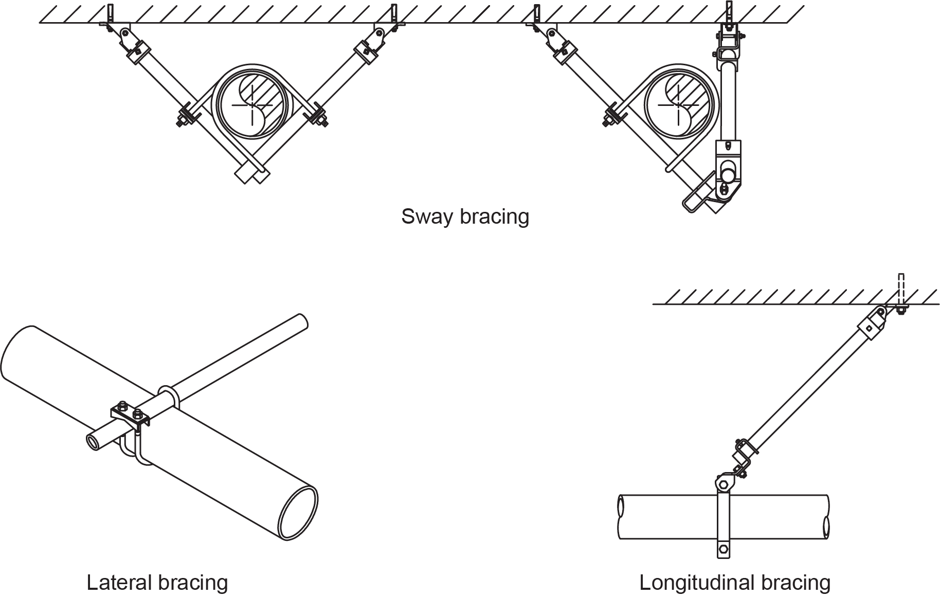
- Typically, piping systems are restrained with rigid braces that run upward at an angle from the pipe to the ceiling. The space required for the installed restraints can cause problems if non-structural walls need to be penetrated or other mechanical components are in the designed load path for the restraints.
Figure 21 shows different seismic restraint assemblies for piping systems.
Mechanical Component Anchorage
The purpose of a seismic restraint is to form a load path between the mechanical component and the building structure. It must be attached to a portion of the building structure capable of carrying the expected seismic loads.
Materials and Installation
Planning for the installation of seismic restraint components early in a project can greatly reduce the cost and complexity of the project. The P. Eng or manufacturer can provide comprehensive shop drawings and details to facilitate proper and cost-effective installation in accordance with existing standards and codes.
Installing seismic restraint hardware and seismic-rated vibration isolators requires the consideration of four aspects of the system:
- Attachment of the equipment to the restraint: the equipment must be securely attached to the restraint, and this attachment must demonstrate sufficient strength to withstand the imposed forces and to allow for transfer of seismic forces into the restraint.
- Restraint design: the strength of the seismic restraint must be sufficient to withstand the equipment-imposed forces.
- Attachment of restraint to the building structure: this attachment is typically via bolts, welds, or concrete anchors. Typically this attachment is the “weakest link” of the overall system, especially when post-installed concrete anchors are used.
- Equipment fragility: the ability of the equipment to continue to operate after being subjected to seismic force. This information must be obtained from the equipment manufacturer.
Joining Practices
Joints and connections in a DWV system must be water- and gas-tight at the required pressure for testing and their intended use. Many different material and joining practices may be used in a DWV system, and specific code requirements apply for each.
Plastic Pipe Transition
- Transition solvent cement shall only be used for joining an ABS drainage system to a PVC drainage system.
Caulked Lead Drainage Joints
- Caulked lead drainage joints shall not be used except for cast-iron pipe in a drainage system or venting system or between such pipe and:
- Other ferrous pipe
- Brass and copper pipe
- A caulking ferrule
- A trap standard
- Every caulked lead drainage joint shall be firmly packed with oakum and tightly caulked with lead to a depth of not less than 25 mm (1 in.).
- No paint, varnish, or other coating shall be applied on the lead until after the joint has been tested.
- A length of hub, spigot pipe, and pipe fillings in a drainage system shall be installed with the hub at the upstream end.
Wiped Joints (Lead Pipe)
- Wiped joints shall not be used except for sheet lead or lead pipe or between such pipe and copper pipe or a ferrule.
- Every wiped joint in straight pipe shall:
- Be made of solder
- Have an exposed surface on each side of the joint of at least 19 mm ([latex]\tfrac{3}{4}[/latex] in.) wide
- Be not less than 10 mm (0.394 in.) thick at the thickest part
- Every wiped flanged joint shall be reinforced with a lead flange not less than 19 mm wide.
Screwed Joints
- When making a screwed joint, the ends of the pipe shall be reamed or filed out to the size of the bore, and all chips and cuttings shall be removed.
- No pipe-joint cement or paint shall be applied to the internal threads.
Flared Joints
- When making a flared joint, the pipe shall be expanded with a proper flaring tool and not be used for hard (drawn) copper tube.
Mechanical Joints (MJ and Victaulic)
- Mechanical joints shall be made with compounded elastomeric rings held in compression by stainless-steel or cast-iron clamps or groove and shoulder-type mechanical couplings.
Cold-Caulked Joints (Cement and Fibre Compound)
- Cold-caulked joints shall not be used except for bell and spigot pipe in a water system, a drainage system, or a venting system.
- Caulking compound used in cold-caulked joints shall be applied according to the manufacturer’s directions.
- Every cold-caulked joint in a drainage system shall be firmly packed with oakum and tightly caulked with cold-caulking compound to a depth of not less than 25 mm (1 in.).
Stainless Steel Welded Joints
- Stainless steel welded joints shall conform to ASME B31.9, “Building Services Piping.”
- Butt weld pipe fittings shall be at least as thick as the wall of the pipe used.
Drilled and Tapped Joints
- Drilled and tapped joints shall not be made in a sanitary drainage pipe or vent pipe and fittings unless suitable provision has been made for drilling and tapping.
Welded Joint Restrictions
- Galvanized steel pipe and fittings as well as cast-iron soil pipe and fittings shall not be welded.
Unions and Slip Joints
- Running thread and packing nut connections and unions with a gasket seal shall not be used downstream of a trap weir in a drainage system or in a venting system.
- A slip joint shall not be used in a venting system or drainage system, except to connect a fixture trap to a fixture drain in an accessible location.
Increasing or Reducing Size
- Every connection between two pipes of different size shall be made with an increaser or a reducer fitting installed so that it will permit the system to be completely drained.
Joining Dissimilar Metals
- Adaptors, connectors, or mechanical joints used to join dissimilar materials shall be designed to accommodate the required transition.
Connection of Floor Outlet Fixtures
- Every pedestal urinal, floor-mounted water closet, or s-trap standard shall be connected to a fixture drain by a floor flange, except a cast-iron trap standard which may be caulked to a cast-iron pipe.
- Every floor flange shall be brass, except that where cast-iron or plastic pipe is used, a floor flange of the same material may be used.
- Every floor flange shall be securely set on a firm base and fastened to the floor or trap flange of the fixture.
- Water-closet bowls shall be securely attached to the floor flange, floor, or wall carrier.
- Every joint in a floor flange shall be sealed with a resilient watertight and gas-tight seal.
- Where a lead water-closet stub is used, the length of the stub below the floor flange shall be not less than 75 mm (3 in.).
Indirect Connections
- Where a fixture or device is indirectly connected, the connections shall be made by terminating the fixture drain above the flood level rim of a directly connected fixture to form an air break.
- The size of the air break shall at least equal the size of the fixture drain, branch, or pipe that terminates above the directly connected fixture, and it shall be not less than 25 mm (1 in.).
 Self-Test D-1.10: Requirements and Prohibitions for DWV Systems
Complete Self-Test D-1.10 and check your answers.
If you are using a printed copy, please find Self-Test D-1.10 and Answer Key at the end of this section. If you prefer, you can scan the QR code with your digital device to go directly to the interactive Self-Test.

References
National Research Council of Canada. (2020). National plumbing code of Canada 2020. Canadian Commission on Building and Fire Codes. https://nrc-publications.canada.ca/eng/view/ft/?id=6e7cabf5-d83e-4efd-9a1c-6515fc7cdc71
Skilled Trades BC. (2021). Book 2: Install fixtures and appliances, install sanitary and storm drainage systems. Plumber apprenticeship program level 2 book 2 (Harmonized). Crown Publications: King’s Printer for British Columbia.
Trades Training BC. (2021). D-1: Install sanitary drain, water and vent systems. In: Plumber Apprenticeship Program: Level 2. Industry Training Authority, BC.
Media Attributions
All figures are used with permission from Skilled Trades BC (2021) unless otherwise noted.
(Grade); The angle or tilt of a pipe that helps waste flow in the right direction, usually downward. (Section D-1.10)
A fitting used to change the direction of the pipe by 90 degrees. (Section D-1.10)
A pit or tank used to collect waste water that can't flow by itself into the sewer. (Section D-1.10)
A one-way flow control valve installed in a drainage system. Backwater valves are required to protect fixtures and drainage openings installed below grade, such as in a basement, where the possibility exists for the municipal sewage or stormwater systems to become overloaded and force wastewater back through your drains. Backwater valves are also required on
any subsoil drainage pipe that connects into the sanitary drain to protect it from sewage backups. Under normal conditions, it allows the wastewater to drain out of the system, but if a reversal of flow should occur, the valve is forced closed and protects the interior of the building from sewage backup. (Figures 4 and 5, Section D-1.2; Section D-2.3)
Plumbing connections where a fixture or device is not directly connected but instead terminates above the flood level rim of a directly connected fixture, forming an air break. This type of connection is designed to prevent backflow. (Section D-1.10)
A device used to trap fats, oils, or grease from wastewater before it enters the drainage system, often used in kitchens, restaurants, or care facilities. (Section D-1.10)
A device installed to capture oil or gasoline in wastewater to prevent it from entering the drainage system. (Section D-1.10)
The components and systems installed to protect mechanical systems, including piping, from seismic forces, ensuring that the system can withstand the stresses of an earthquake. (Section D-1.10)
A type of joint sealed using a caulking compound, often used in bell and spigot pipe systems. The compound must be packed tightly to ensure a gas- and water-tight seal. (Section D-1.10)
A type of piping joint where sections of pipe are fused together through heat, creating a strong, permanent bond. Specific standards, like ASME B31.9, govern their installation in building services. (Section D-1.10)
