D-1.5 Sizing Sanitary Drainage Pipes
Trap arms, fixture drains, branches, stacks, sanitary building drains, sanitary building sewers, and sewage sumps are all part of the sanitary drainage system. Wet vents are part of the drainage and venting systems. Sizing wet vents will be covered in later chapters.
To begin, we must understand that the load that a fixture imposes on the drainage system is measured in fixture units (FU). Each plumbing fixture has an FU rating that is calculated using the rate of discharge, the frequency of use, and the time between each use of a plumbing fixture. The fixture unit rating represents the hydraulic load placed on the sanitary drainage system by that fixture.
Sizing pipe for a drainage system is a relatively straightforward process once you are familiar with the tables provided in the Plumbing Code book. These tables provide the minimum size of all drainage pipes based on the maximum fixture unit load it can carry for any particular size.
Because there are different tables for sizing each drainage pipe designation, you must be able to properly identify the different sections of the drainage system and their function.
Sizing Traps and Fixture Outlet Pipes
The individual fixtures are the place to start whenever you are sizing a drainage system. Table 2.4.9.3 provides two very important pieces of information:
- The fixture unit load imposed on the drainage system based on the type of fixture
- The minimum size of the fixture outlet pipe, which would also determine the minimum size of the trap and fixture drain serving the fixture
Table 2.4.9.3
Table 1 is an excerpt from Table 2.4.9.3 in the National Plumbing Code (NPC) of Canada (2020; Division B 2-31) and provides a list of common plumbing fixtures found in domestic and commercial drainage installations.
| Fixture | Minimum size of fixture outlet pipe (in.) | Hydraulic load (FUs) |
|---|---|---|
| Autopsy table | 1.50 | 2 |
| Bathroom group with flush tank | N/A | 6 |
| Bathroom group with direct flush valve | N/A | 8 |
| Bathtub (with or without shower) | 1.50 | 1.50 |
| Bath: foot, sitz, or slab | N/A | 1.50 |
| Beer cabinet | N/A | 1.50 |
| Bidet | N/A | 1 |
| Domestic clothes washer | N/A | 2 with 2 in. trap |
| Commercial clothes washer | N/A | 2 with 2 in. trap |
| Dental unit or cuspidor | N/A | 1 |
| Domestic dishwasher | N/A | 1.50, no load when connected to garbage grinder or domestic sink |
| Commercial dishwasher | N/A | 3 |
| Drinking fountain | N/A | 0.50 |
| Floor drain | N/A | 2 with 2 in. trap 3 with 3 in. trap |
Hydraulic Load for Floor Drains
Some clarification is needed regarding the hydraulic load assigned to a floor drain. Floor drains can be classified under two general headings:
- Non-emergency floor drains
- Emergency floor drains
Non-Emergency Floor Drains
Non-emergency floor drains are installed in the floor of a structure and are mainly designed to remove any nearby standing water. When installed, the hydraulic load imposed on the drainage system would equal the values listed in Table 2.4.9.3., as shown above. Some floor drains are installed near a wall and are usually equipped with a funnel attached to the strainer. These are also not considered emergency floor drains.
Emergency Floor Drains
Unlike the non-emergency variety, emergency floor drains, by code definition, are in place for overflow protection and do not receive regular discharge. The code also requires — in Division B, Notes to Part 2, A-Table 2.4.9.3. — that any floor drain installed in a washroom be considered an emergency floor drain. When a floor drain is designated as an emergency floor drain, there shall be no hydraulic load assigned to it. This provision allows the 0 FUs emergency floor drain to be connected to the drainage system without imposing additional fixture unit loading that might require an increase in drain pipe size.
If you require sizing information for a fixture that is not listed in Table 2.4.9.3., you must refer to Table 2.4.10.2. The fixture unit loads listed in this table are based on the trap size the fixture employs and not on the type of fixture. If this is the case, you would find the trap size by physically measuring the fixture outlet pipe on site or by referring to the manufacturer’s information. This table would also be used if you were sizing a trap that may be used to serve drains from unspecified equipment on site. In Table 2, you can see that the fixture unit loads are, in most cases, larger than those in Table 2.4.9.3.
Example
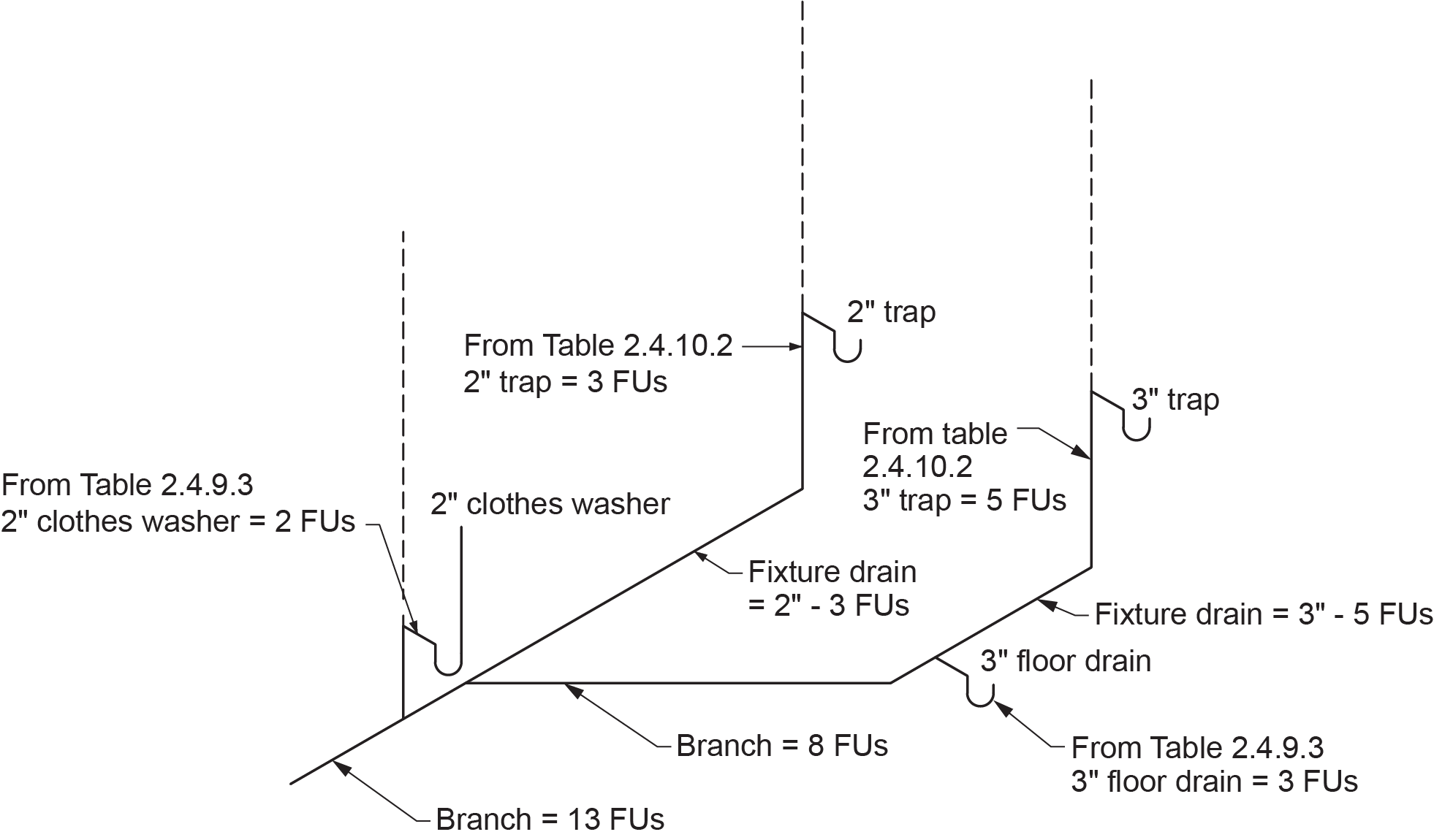
A 3 in. non-emergency floor drain from Table 2.4.9.3. has a hydraulic load of 3 FUs, while the hydraulic load for a 3 in. trap from Table 2.4.10.2 (NPC, 2020, B 2-33) is 5 FUs.
| Trap Size (in.) | Hydraulic Load (FUs) |
|---|---|
| 1.25 | 1 |
| 1.50 | 2 |
| 2 | 3 |
| 3 | 5 |
| 4 | 6 |
The reason for this inflated value is that the 3 in. trap serving as a floor drain will impose a load on the drainage system associated with the floor drain’s function (3 FUs) (Figure 1). The 3 in. trap, on the other hand, could have an unknown flow rate; therefore, a larger FU load is assigned to it.
Hydraulic Load from Fixtures with a Semi-Continuous Flow
Sometimes we need to size a drain receiving flow in litres/second (L/s) from a pump or other piece of equipment. The code is vague regarding a definition difference between continuous and semi-continuous flow and what produces it. When a pump operates and sends discharge to a drainage system, it is assumed that it will not be pumping forever and that it will cycle on and off. For that reason, both continuous and semi-continuous flows are treated the same.
In such cases, we need two pieces of information:
- NPC Sentence 2.4.10.3.(1) is used to convert the pump flow rate (L/s) into fixture unit imposed on the sanitary system by the pump discharge.
- If a trap is required to serve an indirect connection, the trap used to serve the pump discharge is sized using Table 2.4.10.12. (Table 3) in the NPC (2020, B 2-47).
| Trap Size (in.) | Flow (L/s) | Hydraulic Load (FUs) |
|---|---|---|
| 1.50 | 0.00–0.090 | 3 |
| 2 | 0.091–0.190 | 6 |
| 3 | 0.1910–0.850 | 27 |
| 4 | 0.85–5.700 | 180 |
Example
A pump discharges a continuous flow of 0.5 L/s into a sanitary drainage system.
What is:
- The fixture unit load imposed on the system by the pump?
- The trap and fixture drain size to accommodate the pump discharge?
Solution
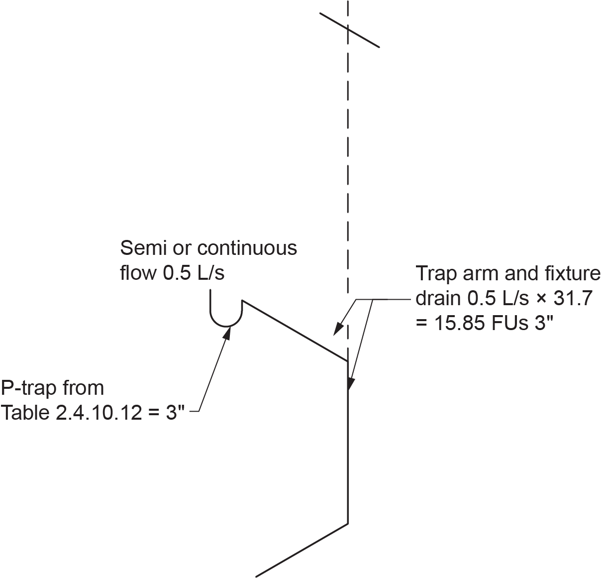
- First, we must covert the L/s discharge flow rate to drainage FUs. Clause 2.4.10.3 in the NPC gives us the conversion needed. It requires the load on a sanitary drainage system to be 31.7 FUs per L/s of flow. Using the equation below, we can determine that the hydraulic load on the system is 15.85 FUs
([latex]0.5\text{ L/s}\times31.7 =15.85\text{ FUs}[/latex]). - With a drainage load of 15.85 FUs, we need to determine the trap size used for this installation. For that component, we use Table 2.4.10.12. For our example with a flow rate of 0.5 L/s, we would look down the centre column until we find a flow rate range that encompasses our flow rate. We can see that the third row with a flow rate ranging from 0.191–0.850 L/s is the proper choice. From this row, we can determine the trap size, which is 3 in.
Note that the table offers a third column, which gives a hydraulic load figure for all of the flow rate ranges. This hydraulic load is based on the maximum flow rate in all of the ranges. If you multiply the maximum flow rate in all of the ranges by 31.7, the product equals the hydraulic load given.
In our example with a flow rate of 0.5 L/s, our hydraulic load is 15.85 FUs and not 27 FUs, which is based on 0.85 L/s (Figure 2). This is the maximum load that can be drained to a 3 in. trap from semi or continuous flow. While the discharge is within the sanitary system, it is considered to be 15.85 FUs and not 0.5 L/s.
Sizing Branches
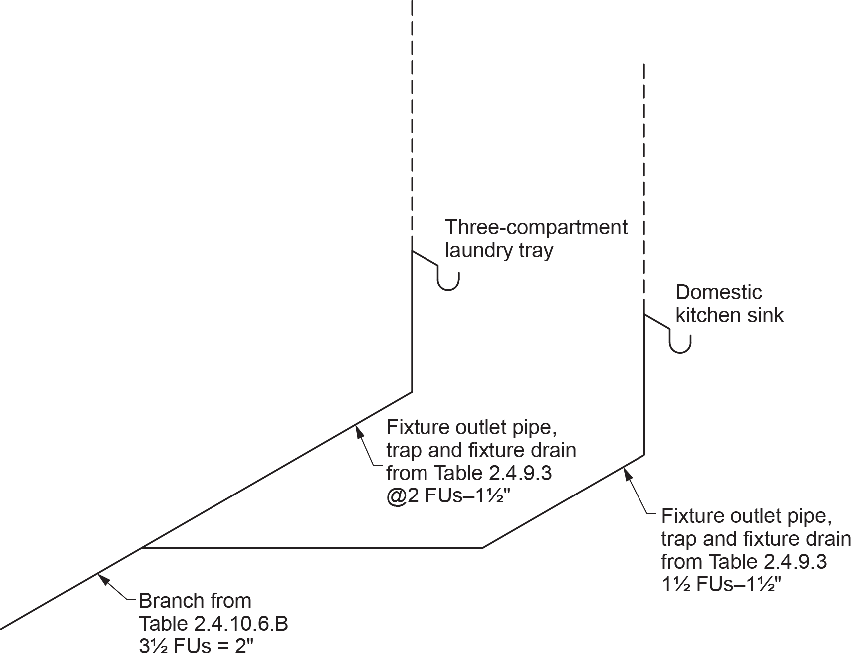
A branch serves two or more fixtures or stack within a storey and may connect to another branch, building drain, sewage sump, or stack (Figure 3). When sizing a branch, use Table 2.4.10.6.-B to size each portion of the branch as the fixture load is applied, as shown in Table 4.
| Branch Size (in.) | Maximum Hydraulic Load (FUs) |
|---|---|
| 1.25 | 2 |
| 1.50 | 3 |
| 2 | 6 |
| 3 | 27 |
| 4 | 180 |
| 5 | 390 |
| 6 | 700 |
| 8 | 1,600 |
| 10 | 2,500 |
| 12 | 3,900 |
Sizing Stacks
A stack (also known as a soil-or-waste stack or SOWS) is a drainage pipe that passes through at least one storey as a drain pipe; this also includes any nominally horizontal offsets. A stack will typically receive waste from multiple fixtures connected to it. These may be located on a single floor or multiple storeys.
When sizing a stack, you would use Table 2.4.10.6.-A (Table 5). Notice that it states not only the maximum load that the stack can carry for any given size but also the maximum number of fixture units drained to it from any one storey for any given size.
| Stack Size (in.) | Maximum Hydraulic Load (FUs) | Maximum FUs Drained From Any One Storey |
|---|---|---|
| 1.25 | 2 | 2 |
| 1.50 | 8 | 2 |
| 2 | 24 | 6 |
| 3 | 102 | 18 |
| 4 | 540 | 100 |
| 5 | 1,400 | 250 |
| 6 | 2,900 | 500 |
| 8 | 7,600 | 830 |
| 10 | 15,000 | 2,700 |
| 12 | 26,000 | 4,680 |
| 15 | 50,000 | 9,000 |
Example
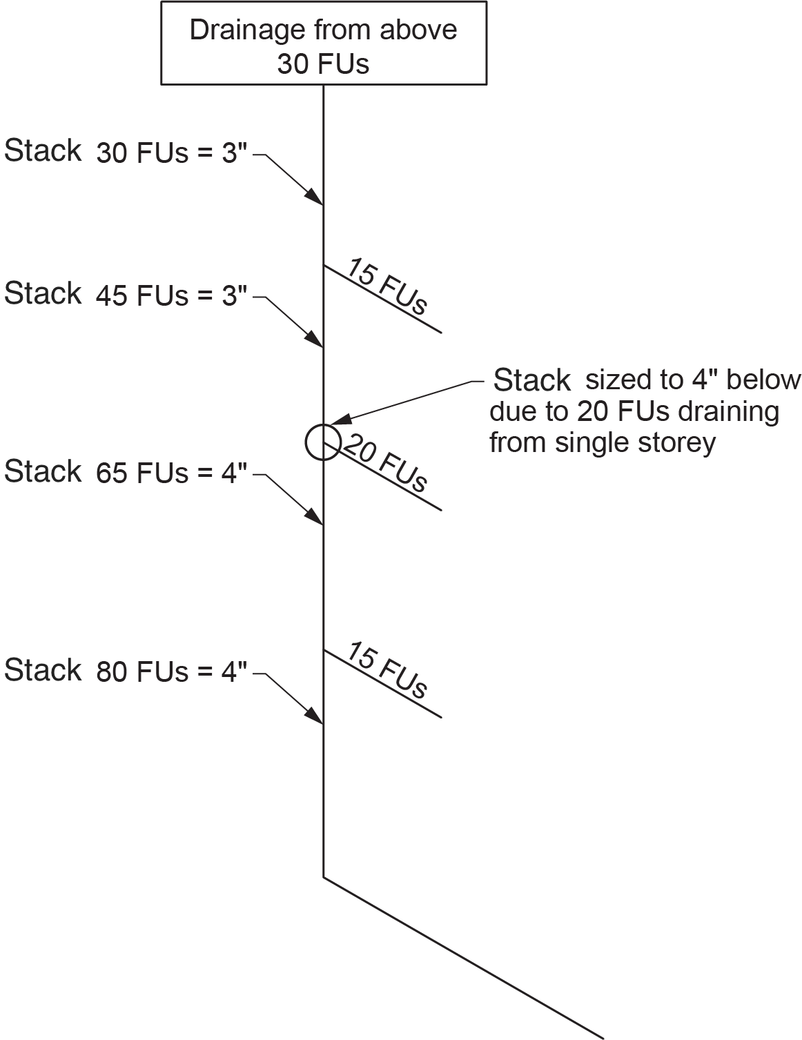
A 3 in. stack can have a maximum load of 102 FUs in total. If the 3 in. stack receives a 20-FU load from any one storey, then the size of the stack would have to be 4 in. from that floor’s connection point downward because, according to the third column of Table 2.4.10.6.-A, the maximum load from any one storey draining to a 3 in. stack is 18 FUs (Figure 4).
Sizing a Sanitary Building Drain or Sewer
The sanitary building drain conducts sewage from the furthest upstream fixture drain, branch, or stack serving a water closet and terminates 1 meter (39 inches) outside the foundation. At this point, the sanitary building sewer is established and conducts the flow to the municipal disposal system or private disposal system.
To determine the size of any portion of the sanitary building drain or building sewer, you must know the drainage load and the pipe grade. Notice that for any pipe size, the load-carrying capacity of the pipe increases as the grade increases.
| Size of Drain or Sewer (in.) | Maximum Hydraulic Load (FUs) | |||||
|---|---|---|---|---|---|---|
| Slope | ||||||
| 1 in 400 | 1 in 200 | 1 in 133 | 1 in 100 | 1 in 50 | 1 in 25 | |
| 3 | N/A | N/A | N/A | N/A | 27 | 36 |
| 4 | N/A | N/A | N/A | 180 | 240 | 300 |
| 5 | N/A | N/A | 380 | 390 | 480 | 670 |
| 6 | N/A | N/A | 600 | 700 | 840 | 1,300 |
| 8 | N/A | 1,400 | 1,500 | 1,600 | 2,250 | 3,370 |
| 10 | N/A | 2,500 | 2,700 | 3,000 | 4,500 | 6,500 |
| 12 | 2,240 | 3,900 | 4,500 | 5,400 | 8,300 | 13,000 |
| 15 | 4,800 | 7,000 | 9,300 | 10,400 | 16,300 | 22,500 |
Sizing the System
Now that the different tables have been explored, it is time to use them to size the entire sanitary system.
Sizing fixture drains:
- Fixture drains serve one fixture only and may run vertically or horizontally.
- The size of every fixture drain that serves a water closet must be at least 3 in., except for a macerating toilet, which must be at least [latex]\tfrac{3}{4}[/latex] in.
- Fixture drains begin at the trap weir and end at the connection point to a branch, stack, or sanitary building drain.
- The minimum size of a fixture drain is equal to the fixture outlet pipe and trap found in NPC Table 2.4.9.3. and 2.4.10.2.
- A fixture drain, fixture outlet pipe, and trap serving a semi or continuous flow fixture is sized from NPC Table 2.4.10.12.
- The portion of the fixture outlet pipe, trap arm, and fixture drain serving three or more compartments of a sink shall be increased one size larger than the largest fixture outlet pipe located upstream.
- The size of the fixture drain must not be smaller than the size of the individual vent connected to it.
- As long as proper grade and cleanout spacing are provided, there is no restriction to the length of a fixture drain.
Sizing branches:
- The size of a branch is found in Table 2.4.10.6.-B.
- The size of the branch shall not be smaller than the size of any vent connected to it.
- The load to consider on any section of a branch is the sum of the loads actually connected to — or future connections to — the branch upstream of the section being sized.
- A branch may never be smaller than any upstream drainage pipe connecting to the branch.
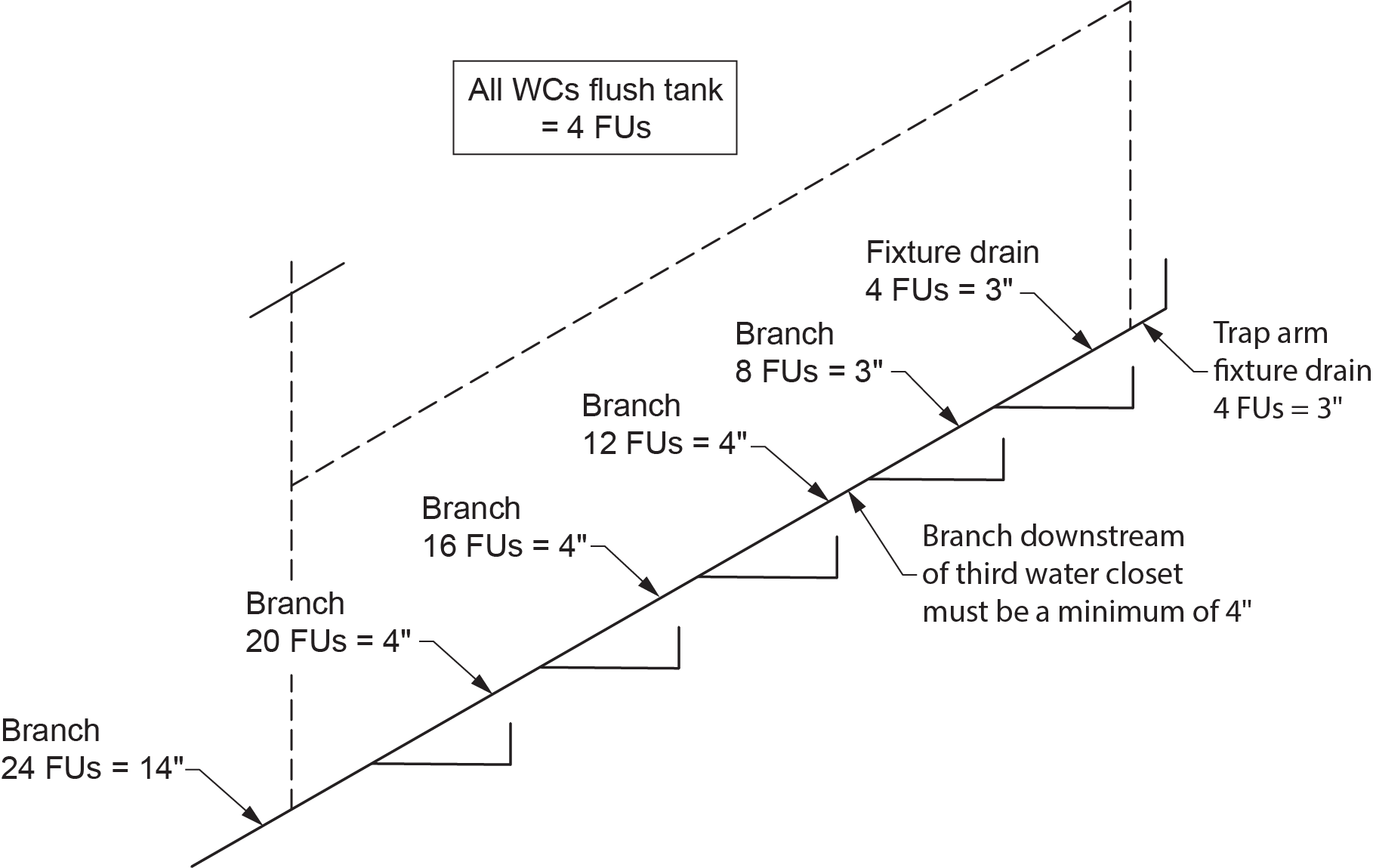
- Branches downstream of where a third water closet is connected must be 100 mm (4 in.) (Figure 5).
- As long as proper grade and cleanout spacing are provided, there is no restriction to the length of a branch
Fixture Unit Loads on Branches Serving Bathroom Groups
The NPC (Table 2.4.9.3.) requires that the drainage load imposed on the drainage system by bathroom groups are as follows:
- With flush tank water closet = 6 FUs
- With flush valve water closet = 8 FUs
These listed drainage fixture unit values reflect the load of entire bathroom groups on the sanitary drainage system. A closer look at these values shows that they are slightly lower than the total of all fixture unit loads of the fixtures that make up the bathroom group. The reason for this difference is that a diversity factor is placed on a bathroom group. In other words, the probability of all fixtures in the group discharging at once is extremely low, so the load imposed on the system can be reduced.
For example, suppose we have a standard bathroom group consisting of:
- A flush tank water closet (WC)
- An [latex]1\tfrac{1}{4}[/latex] in. lavatory basin
- A bathtub
The drainage fixture unit load total of all of the individual fixtures listed above would equal:
| Fixture | Drain Load (FUs) |
|---|---|
| WC with flush tank | 4 |
| 1.25 in. lavatory basin | 1 |
| Bathtub | 1.50 |
| Total | 6.50 |
In this case, by designating the fixtures as a bathroom group, the load is reduced by 0.50 FUs.
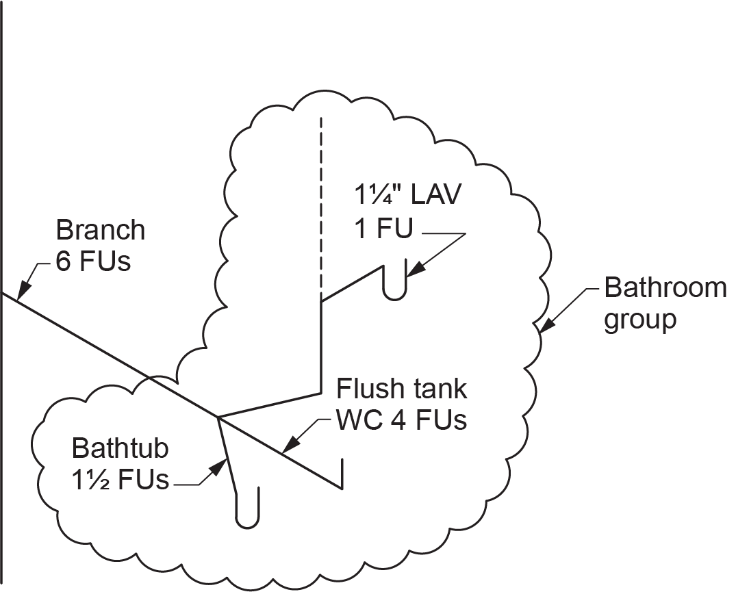
Whenever the opportunity presents itself, you should always use the reduced bathroom group values, as doing so will lower the total load on the DWV system. When you are sizing your drainage drawings, a good practice to employ is to identify all bathroom groups on your drawings with a circle or a cloud, as shown in Figure 6. This will help to indicate where load reduction may be utilized.
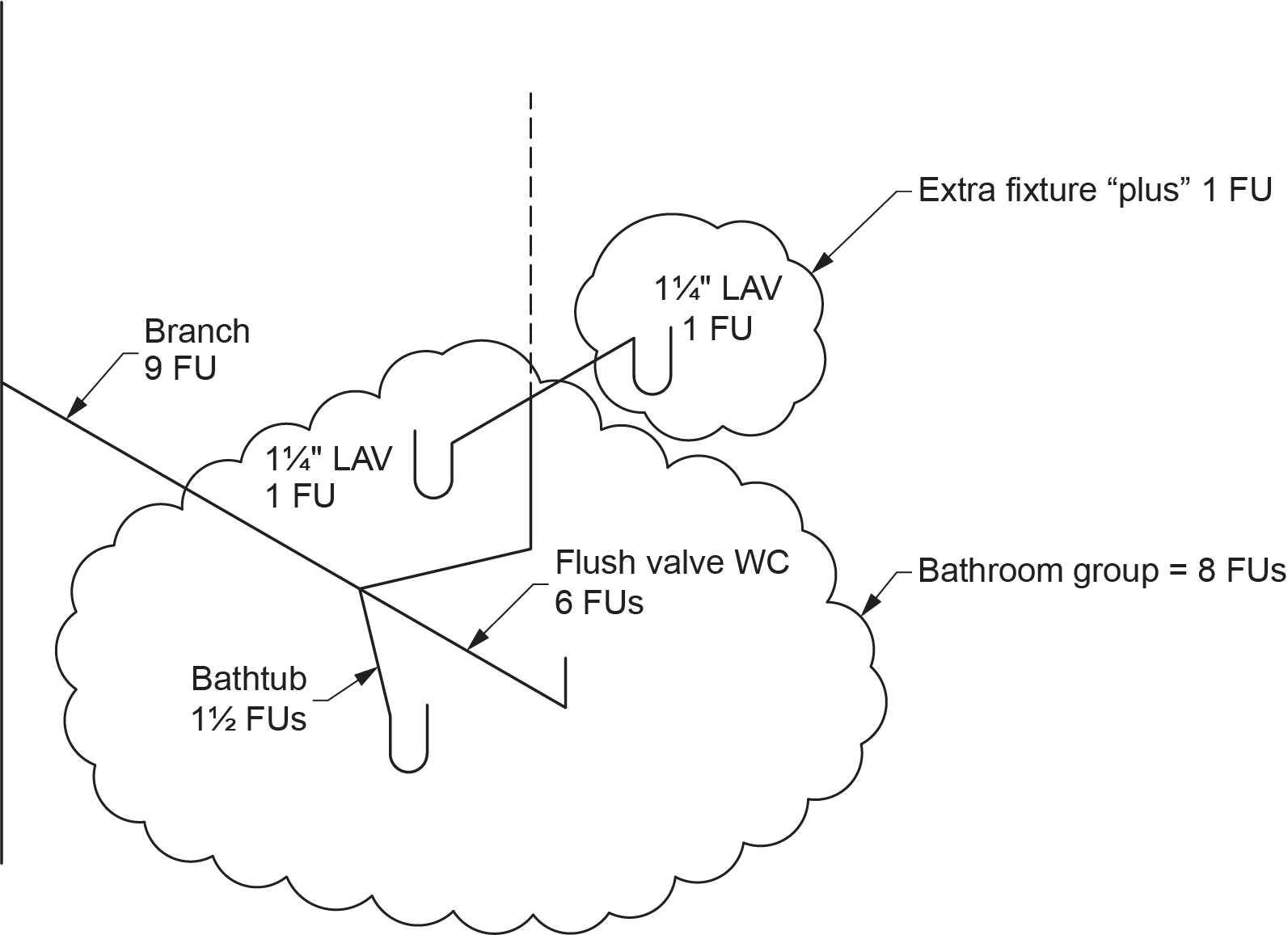
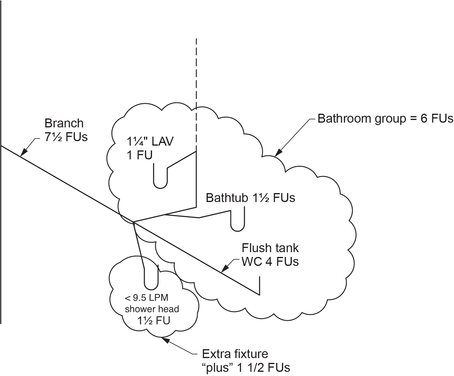
Fixture Unit Loads on Branches Serving Bathroom Groups with Additional Fixtures
The branch for a four- or five-piece bathroom has an additional fixture(s) that fall outside the NPC definition of a bathroom group. In order to gain the benefit of load reduction, you simply indicate the original bathroom group and add the fixture unit value of the additional fixture(s). The load on the branch serving the group is often referred to as a “bathroom group plus 1 in.” or a “bathroom group plus 1.50 in.” (Figures 7 and 8).
Sizing stacks:
- The size of any section of a stack is found in Table 2.4.10.6.-A (NPC, 2020, B 2-34).
- A stack may never be smaller than any upstream drainage pipe connecting to the stack.
- The size of the stack shall not be smaller than the size of the stack vent connected to it.
- The size of any section of a stack is limited to a maximum number of fixture units draining to the stack from any one storey, as found in the third column of Table 2.4.10.6.-A.
- The load to consider on any section of a stack is the sum of the loads draining to the stack section from above.
- When a nominally horizontal offset in a stack is 1.5 m (5 ft) or more in length (Figure 9), the offset shall be sized as a branch using Table 2.4.10.6.-B (NPC, 2020, B 2-35) or a building drain using Table 2.4.10.6.-C (NPC, 2020, B 2-35). If the size of the offset in the two tables differs, the language states to go with “whichever is less restrictive”. This is meant to be taken in a legal context, which translates to “whichever is larger.” In the case of Figure 9, the offset would need to be increased to 4 in. due to both the table loads as well as the fact it is treated as a branch serving more than two water closets. If the offset increases in size, the larger stack size must be maintained due to the no reduction in drainage pipe size rule.
- A stack serving more than six water closets must be a minimum of 100 mm (4 in.).
Sizing a sanitary building drain or sewer:
- The size of any section of a sanitary building drain or sewer is found in Table 2.4.10.6.-C using the hydraulic load draining to the section and the grade on the building drain or sewer.
- A sanitary building drain or sewer downstream of a main building cleanout fitting must be 100 mm (4 in.) in size.
- A sanitary building drain or sewer downstream of the third water close connected must be 100 mm (4 in.).
- A sanitary building drain or sewer may never be smaller than any upstream drainage pipe connecting to it.
- The load to consider on any section of the sanitary building drain or sewer is the sum of the loads actually connected to — or future connections to — the sanitary building drain or sewer upstream of the section being sized.
- If the building drain or sewer receives discharge from a sewage sump basin (Figure 10), the load to consider would be based on the load imposed by the sewage ejector pump not the FU load of the fixtures draining to the sump basin. For this example, the calculated load of the 2 in. discharge pipe would be:
[latex]0.75\text{ L/s}\times31.7=23.78\text{ FUs }(24\text{ FUs})[/latex] - As long as proper grade and cleanouts are provided, there is no restriction to the length of a sanitary building drain or sewer.
 Self-Test D-1.5: Sizing Sanitary Drainage Pipes
Complete Self-Test D-1.5 and check your answers.
If you are using a printed copy, please find Self-Test D-1.5 and Answer Key at the end of this section. If you prefer, you can scan the QR code with your digital device to go directly to the interactive Self-Test.

References
National Research Council of Canada. (2020). National plumbing code of Canada 2020. Canadian Commission on Building and Fire Codes. https://nrc-publications.canada.ca/eng/view/ft/?id=6e7cabf5-d83e-4efd-9a1c-6515fc7cdc71
Skilled Trades BC. (2021). Book 2: Install fixtures and appliances, install sanitary and storm drainage systems. Plumber apprenticeship program level 2 book 2 (Harmonized). Crown Publications: King’s Printer for British Columbia.
Trades Training BC. (2021). D-1: Install sanitary drain, water and vent systems. In: Plumber Apprenticeship Program: Level 2. Industry Training Authority, BC.
Media Attributions
All figures are used with permission from Skilled Trades BC (2021) unless otherwise noted.
The amount of water moving through a system, like pipes or drains, over a certain time. Imagine pouring water into a funnel—if you pour too much too fast, it overflows. In plumbing and wastewater systems, hydraulic load helps us understand how much water a system can handle before it gets too full or backs up. (Section D-1.5)
A way to measure how much water a plumbing fixture, like a sink or toilet, uses. It helps plumbers figure out how big the pipes need to be to handle the amount of water that flows through them. Each fixture has a specific number of fixture units based on how much water it uses. The higher the number of fixture units, the more water the fixture needs. (Section D-1.5)
A drainage fixture installed in areas prone to accidental water discharge, such as washrooms, mechanical rooms, laundry rooms, and commercial kitchens. Its purpose is to provide overflow protection by directing excess water to the drainage system, preventing flooding and water damage. Unlike regular floor drains, emergency floor drains are typically used as a backup and may remain dry under normal conditions. (Section D-1.5)
When something moves in a steady way but with small breaks. In water systems, semi-continuous flow means water or waste moves through pipes or tanks in regular amounts, but not nonstop. (Section D-1.5)
