Self-Test D-1.9 Sizing Stack Vents, Vent Stacks, and Headers
Complete Self-Test D-1.9 and check your answers.
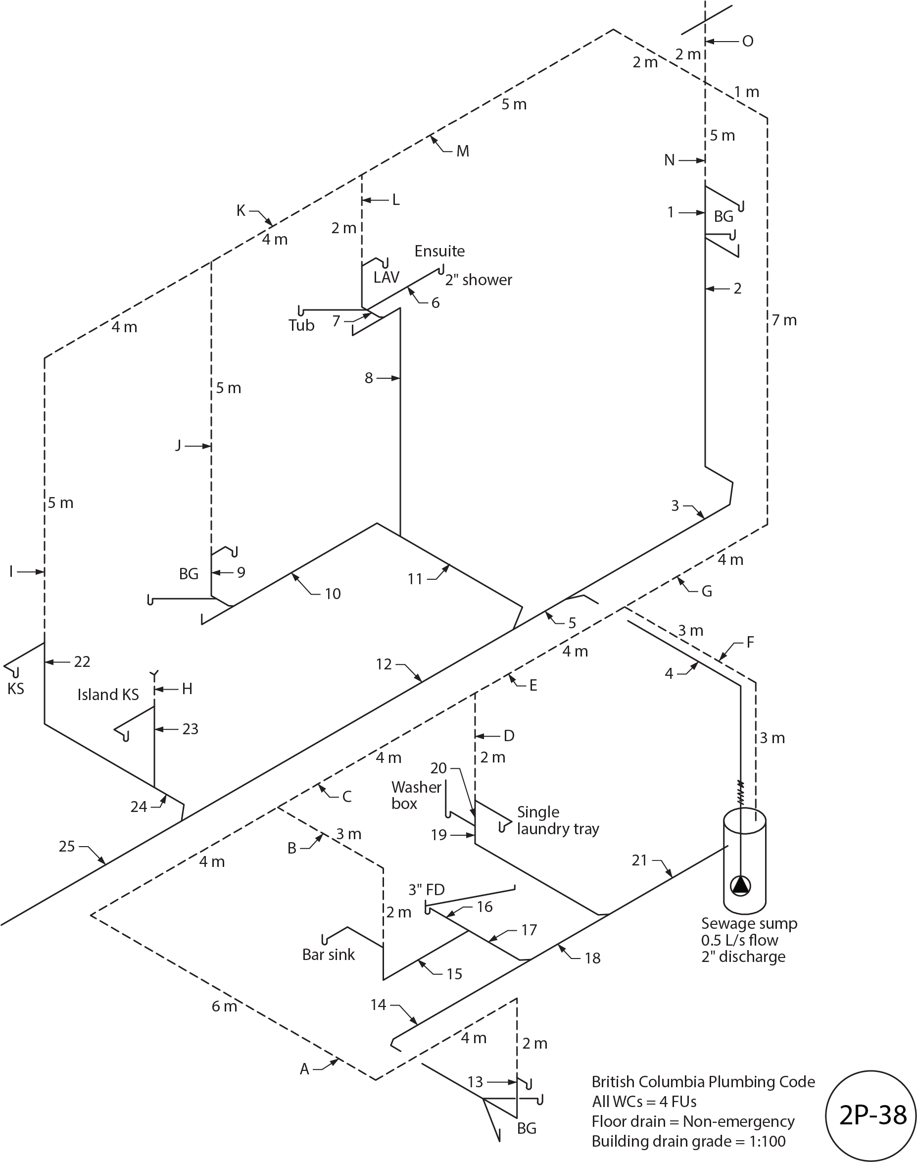 Figure 2P-38
- Using Figure 2P-38, fill in Table 1 by identifying and sizing the DWV drainage installation indicated by the numbers.
Table 1
| Number |
Name |
Hydraulic Load (FU) |
Size |
| 1 |
|
|
|
| 2 |
|
|
|
| 3 |
|
|
|
| 4 |
|
|
|
| 5 |
|
|
|
| 6 |
|
|
|
| 7 |
|
|
|
| 8 |
|
|
|
| 9 |
|
|
|
| 10 |
|
|
|
| 11 |
|
|
|
| 12 |
|
|
|
| 13 |
|
|
|
| 14 |
|
|
|
| 15 |
|
|
|
| 16 |
|
|
|
| 17 |
|
|
|
| 18 |
|
|
|
| 19 |
|
|
|
| 20 |
|
|
|
| 21 |
|
|
|
| 22 |
|
|
|
| 23 |
|
|
|
| 24 |
|
|
|
| 25 |
|
|
|
- Using Figure 2P-38, fill in Table 2 by identifying and sizing the DWV venting installation indicated by the letters.
Table 2
| Letter |
Name |
Hydraulic Load (FU) |
Length |
Size |
| A |
|
|
|
|
| B |
|
|
|
|
| C |
|
|
|
|
| D |
|
|
|
|
| E |
|
|
|
|
| F |
|
|
|
|
| G |
|
|
|
|
| H |
|
|
|
|
| I |
|
|
|
|
| J |
|
|
|
|
| K |
|
|
|
|
| L |
|
|
|
|
| M |
|
|
|
|
| N |
|
|
|
|
| O |
|
|
|
|
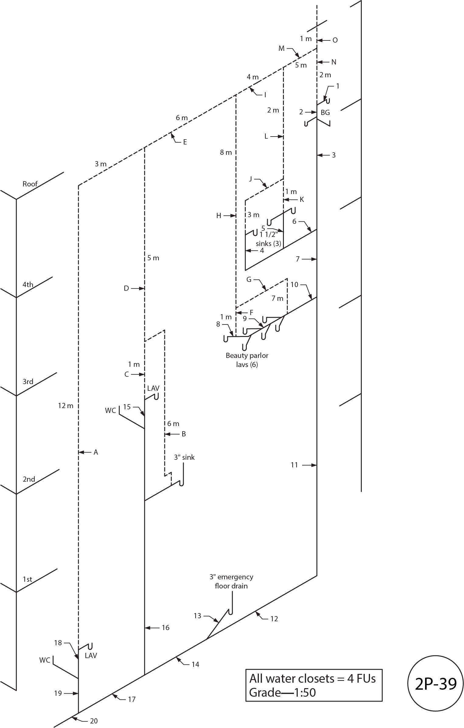 Figure 2P-39
- Using Figure 2P-39, fill in Table 3 by identifying and sizing the DWV drainage installation indicated by the numbers.
Table 3
| Number |
Name |
Hydraulic Load (FU) |
Size |
| 1 |
|
|
|
| 2 |
|
|
|
| 3 |
|
|
|
| 4 |
|
|
|
| 5 |
|
|
|
| 6 |
|
|
|
| 7 |
|
|
|
| 8 |
|
|
|
| 9 |
|
|
|
| 10 |
|
|
|
| 11 |
|
|
|
| 12 |
|
|
|
| 13 |
|
|
|
| 14 |
|
|
|
| 15 |
|
|
|
| 16 |
|
|
|
| 17 |
|
|
|
| 18 |
|
|
|
| 19 |
|
|
|
| 20 |
|
|
|
- Using Figure 2P-39, fill in Table 4 by identifying and sizing the DWV venting installation indicated by the letters.
Table 4
| Letter |
Name |
Hydraulic Load (FU) |
Length |
Size |
| A |
|
|
|
|
| B |
|
|
|
|
| C |
|
|
|
|
| D |
|
|
|
|
| E |
|
|
|
|
| F |
|
|
|
|
| G |
|
|
|
|
| H |
|
|
|
|
| I |
|
|
|
|
| J |
|
|
|
|
| K |
|
|
|
|
| L |
|
|
|
|
| M |
|
|
|
|
| N |
|
|
|
|
| O |
|
|
|
|
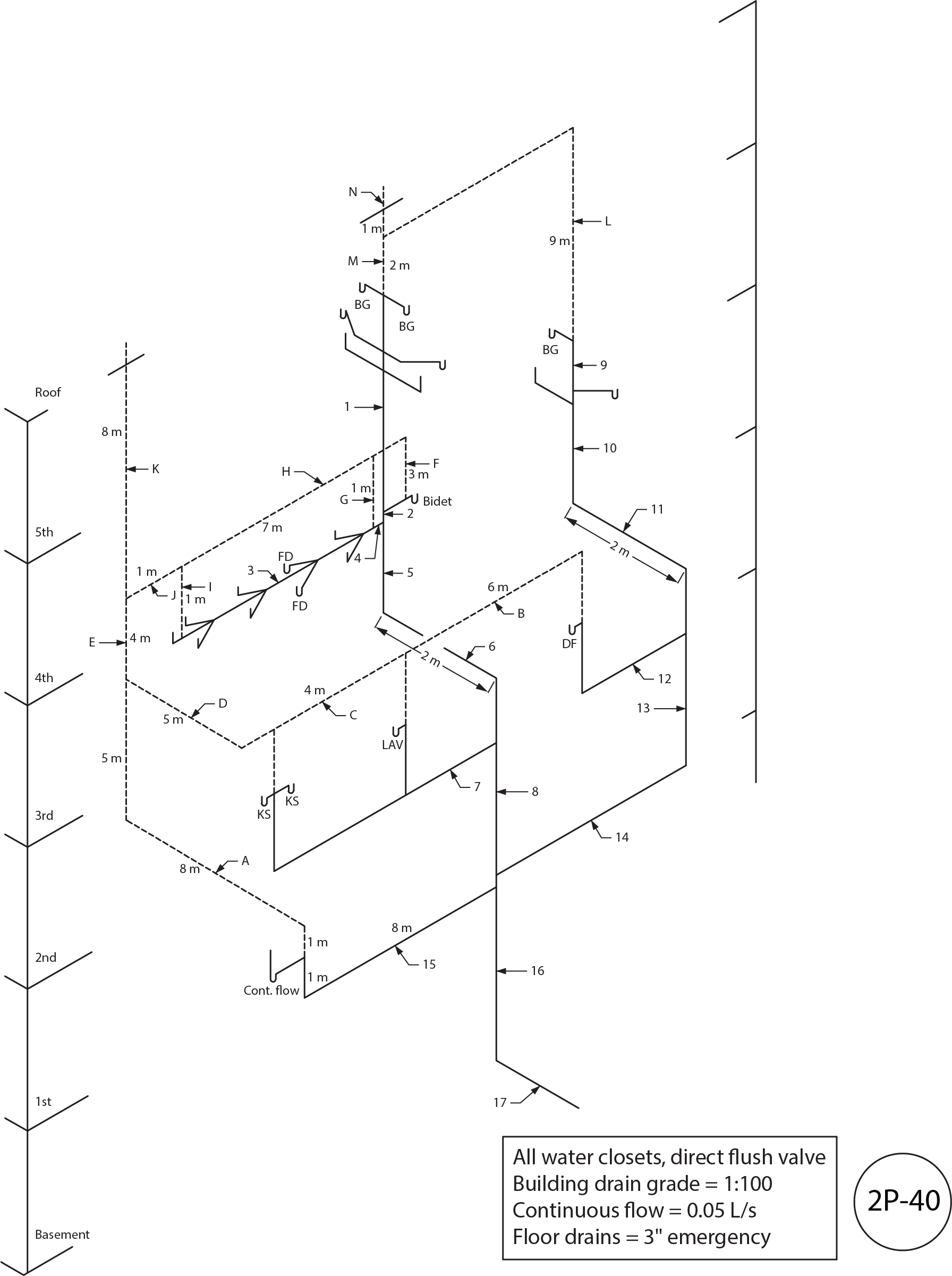 Figure 2P-40
- Using Figure 2P-40, fill in Table 5 by identifying and sizing the DWV drainage installation indicated by the numbers.
Table 5
| Number |
Name |
Hydraulic Load (FU) |
Size |
| 1 |
|
|
|
| 2 |
|
|
|
| 3 |
|
|
|
| 4 |
|
|
|
| 5 |
|
|
|
| 6 |
|
|
|
| 7 |
|
|
|
| 8 |
|
|
|
| 9 |
|
|
|
| 10 |
|
|
|
| 11 |
|
|
|
| 12 |
|
|
|
| 13 |
|
|
|
| 14 |
|
|
|
| 15 |
|
|
|
| 16 |
|
|
|
| 17 |
|
|
|
- Using Figure 2P-40, fill in Table 6 by identifying and sizing the DWV venting installation indicated by the letters.
Table 6
| Letter |
Name |
Hydraulic Load (FU) |
Length |
Size |
| A |
|
|
|
|
| B |
|
|
|
|
| C |
|
|
|
|
| D |
|
|
|
|
| E |
|
|
|
|
| F |
|
|
|
|
| G |
|
|
|
|
| H |
|
|
|
|
| I |
|
|
|
|
| J |
|
|
|
|
| K |
|
|
|
|
| L |
|
|
|
|
| M |
|
|
|
|
| N |
|
|
|
|
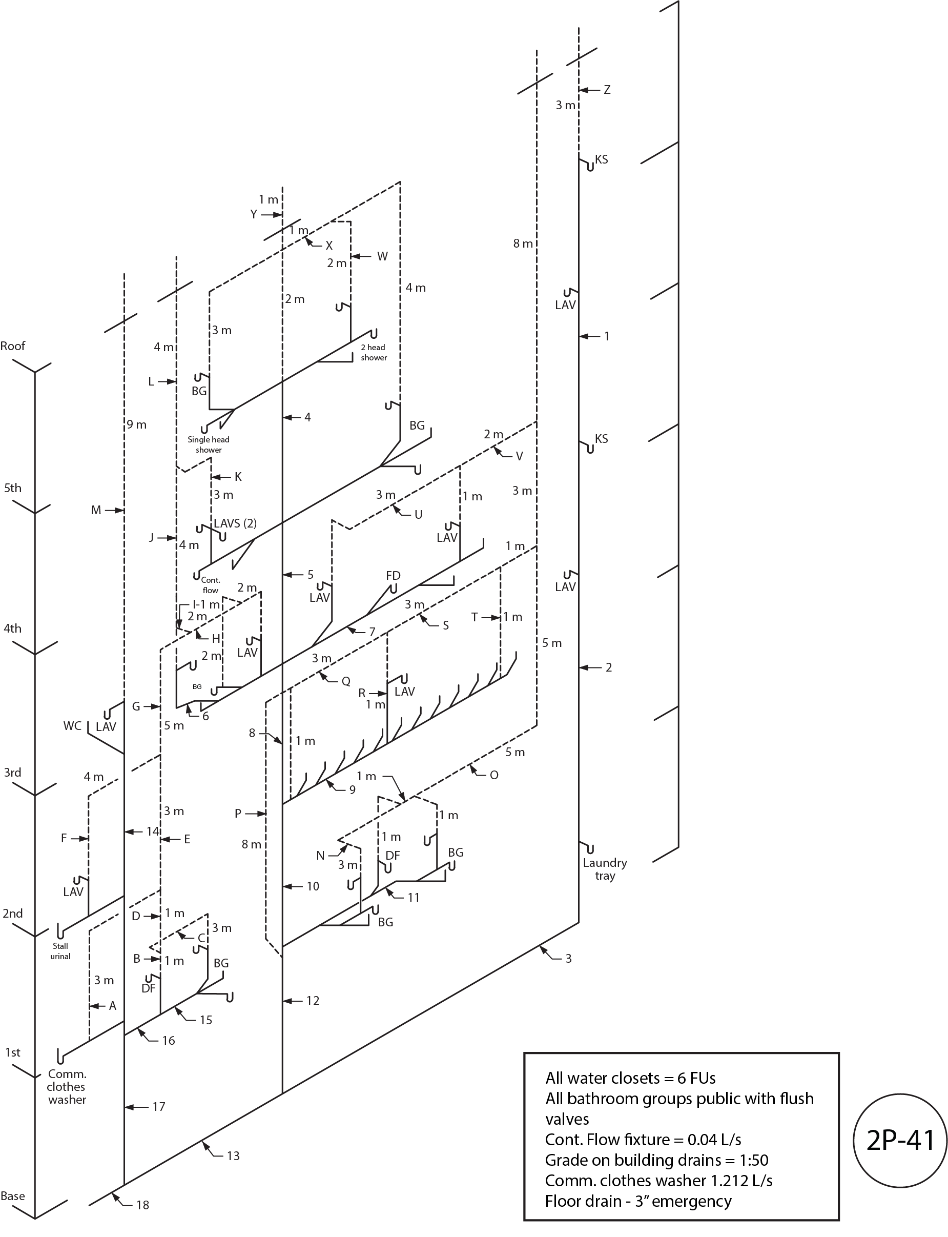 Figure 2P-41
- Using Figure 2P-41, fill in Table 7 by identifying and sizing the DWV drainage installation indicated by the numbers.
Table 7
| Number |
Name |
Hydraulic Load (FU) |
Size |
| 1 |
|
|
|
| 2 |
|
|
|
| 3 |
|
|
|
| 4 |
|
|
|
| 5 |
|
|
|
| 6 |
|
|
|
| 7 |
|
|
|
| 8 |
|
|
|
| 9 |
|
|
|
| 10 |
|
|
|
| 11 |
|
|
|
| 12 |
|
|
|
| 13 |
|
|
|
| 14 |
|
|
|
| 15 |
|
|
|
| 16 |
|
|
|
| 17 |
|
|
|
| 18 |
|
|
|
- Using Figure 2P-41, fill in Table 8 by identifying and sizing the DWV venting installation indicated by the letters.
Table 8
| Letter |
Name |
Hydraulic Load (FU) |
Length |
Size |
| A |
|
|
|
|
| B |
|
|
|
|
| C |
|
|
|
|
| D |
|
|
|
|
| E |
|
|
|
|
| F |
|
|
|
|
| G |
|
|
|
|
| H |
|
|
|
|
| I |
|
|
|
|
| J |
|
|
|
|
| K |
|
|
|
|
| L |
|
|
|
|
| M |
|
|
|
|
| N |
|
|
|
|
| O |
|
|
|
|
| P |
|
|
|
|
| Q |
|
|
|
|
| R |
|
|
|
|
| S |
|
|
|
|
| T |
|
|
|
|
| U |
|
|
|
|
| V |
|
|
|
|
| W |
|
|
|
|
| X |
|
|
|
|
| Y |
|
|
|
|
| Z |
|
|
|
|
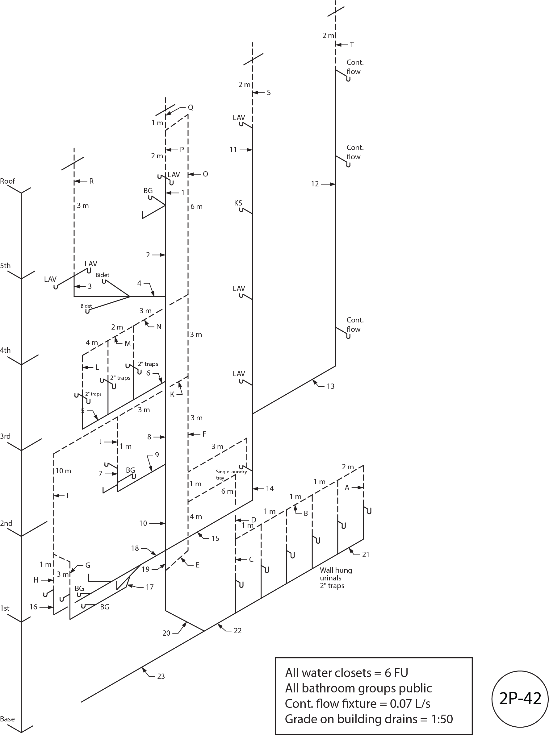 Figure 2P-42
- Using Figure 2P-42, fill in Table 9 by identifying and sizing the DWV drainage installation indicated by the numbers.
Table 9
| Number |
Name |
Hydraulic Load (FU) |
Size |
| 1 |
|
|
|
| 2 |
|
|
|
| 3 |
|
|
|
| 4 |
|
|
|
| 5 |
|
|
|
| 6 |
|
|
|
| 7 |
|
|
|
| 8 |
|
|
|
| 9 |
|
|
|
| 10 |
|
|
|
| 11 |
|
|
|
| 12 |
|
|
|
| 13 |
|
|
|
| 14 |
|
|
|
| 15 |
|
|
|
| 16 |
|
|
|
| 17 |
|
|
|
| 18 |
|
|
|
| 19 |
|
|
|
| 20 |
|
|
|
| 21 |
|
|
|
| 22 |
|
|
|
| 23 |
|
|
|
- Using Figure 2P-42, fill in Table 10 by identifying and sizing the DWV venting installation indicated by the letters.
Table 10
| Letter |
Name |
Hydraulic Load (FU) |
Length |
Size |
| A |
|
|
|
|
| B |
|
|
|
|
| C |
|
|
|
|
| D |
|
|
|
|
| E |
|
|
|
|
| F |
|
|
|
|
| G |
|
|
|
|
| H |
|
|
|
|
| I |
|
|
|
|
| J |
|
|
|
|
| K |
|
|
|
|
| L |
|
|
|
|
| M |
|
|
|
|
| N |
|
|
|
|
| O |
|
|
|
|
| P |
|
|
|
|
| Q |
|
|
|
|
| R |
|
|
|
|
| S |
|
|
|
|
| T |
|
|
|
|
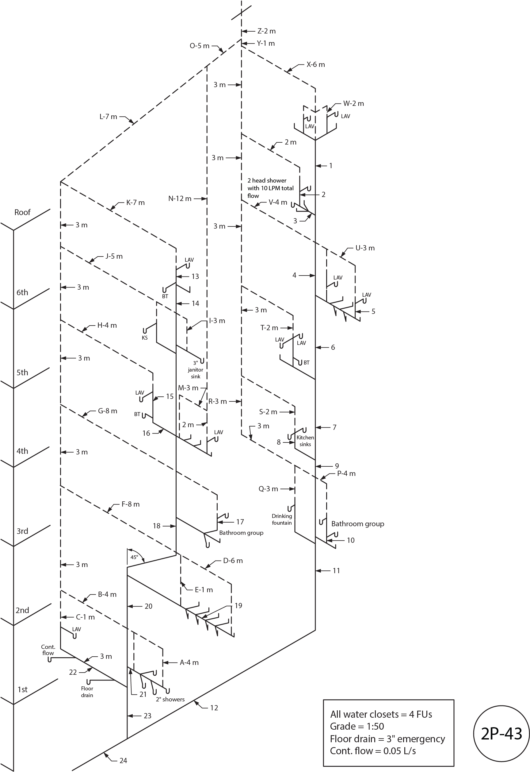 Figure 2P-43
- Using Figure 2P-43, fill in Table 11 by identifying and sizing the DWV drainage installation indicated by the numbers.
Table 11
| Number |
Name |
Hydraulic Load (FU) |
Size |
| 1 |
|
|
|
| 2 |
|
|
|
| 3 |
|
|
|
| 4 |
|
|
|
| 5 |
|
|
|
| 6 |
|
|
|
| 7 |
|
|
|
| 8 |
|
|
|
| 9 |
|
|
|
| 10 |
|
|
|
| 11 |
|
|
|
| 12 |
|
|
|
| 13 |
|
|
|
| 14 |
|
|
|
| 15 |
|
|
|
| 16 |
|
|
|
| 17 |
|
|
|
| 18 |
|
|
|
| 19 |
|
|
|
| 20 |
|
|
|
| 21 |
|
|
|
| 22 |
|
|
|
| 23 |
|
|
|
| 24 |
|
|
|
- Using Figure 2P-43, fill in Table 12 by identifying and sizing the DWV venting installation indicated by the letters.
Table 12
| Letter |
Name |
Hydraulic Load (FU) |
Length |
Size |
| A |
|
|
|
|
| B |
|
|
|
|
| C |
|
|
|
|
| D |
|
|
|
|
| E |
|
|
|
|
| F |
|
|
|
|
| G |
|
|
|
|
| H |
|
|
|
|
| I |
|
|
|
|
| J |
|
|
|
|
| K |
|
|
|
|
| L |
|
|
|
|
| M |
|
|
|
|
| N |
|
|
|
|
| O |
|
|
|
|
| P |
|
|
|
|
| Q |
|
|
|
|
| R |
|
|
|
|
| S |
|
|
|
|
| T |
|
|
|
|
| U |
|
|
|
|
| V |
|
|
|
|
| W |
|
|
|
|
| X |
|
|
|
|
| Y |
|
|
|
|
| Z |
|
|
|
|
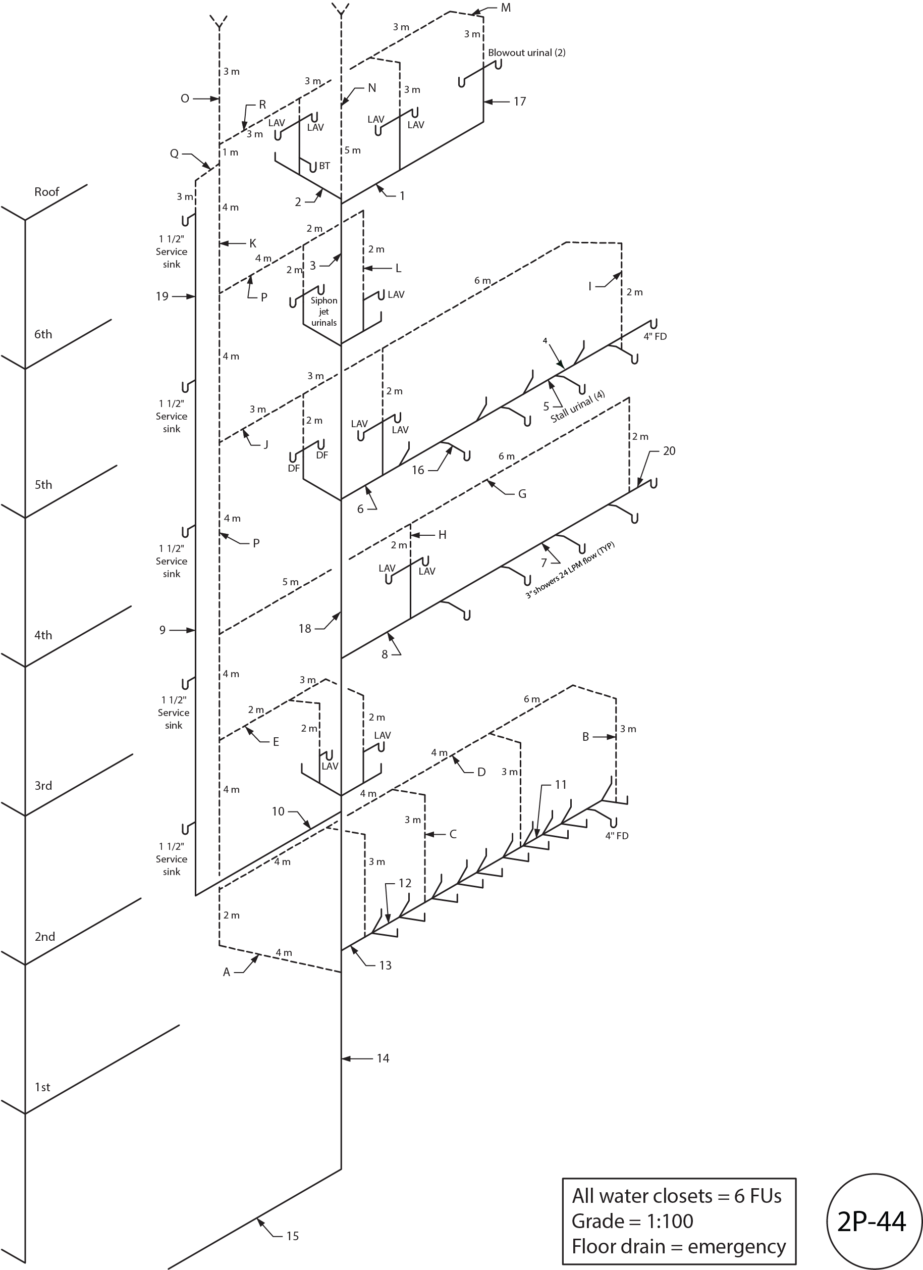 Figure 2P-44
- Using Figure 2P-44, fill in Table 13 by identifying and sizing the DWV drainage installation indicated by the numbers.
Table 13
| Number |
Name |
Hydraulic Load (FU) |
Size |
| 1 |
|
|
|
| 2 |
|
|
|
| 3 |
|
|
|
| 4 |
|
|
|
| 5 |
|
|
|
| 6 |
|
|
|
| 7 |
|
|
|
| 8 |
|
|
|
| 9 |
|
|
|
| 10 |
|
|
|
| 11 |
|
|
|
| 12 |
|
|
|
| 13 |
|
|
|
| 14 |
|
|
|
| 15 |
|
|
|
| 16 |
|
|
|
| 17 |
|
|
|
| 18 |
|
|
|
| 19 |
|
|
|
| 20 |
|
|
|
- Using Figure 2P-44, fill in Table 14 by identifying and sizing the DWV venting installation indicated by the letters.
Table 14
| Letter |
Name |
Hydraulic Load (FU) |
Length |
Size |
| A |
|
|
|
|
| B |
|
|
|
|
| C |
|
|
|
|
| D |
|
|
|
|
| E |
|
|
|
|
| F |
|
|
|
|
| G |
|
|
|
|
| H |
|
|
|
|
| I |
|
|
|
|
| J |
|
|
|
|
| K |
|
|
|
|
| L |
|
|
|
|
| M |
|
|
|
|
| N |
|
|
|
|
| O |
|
|
|
|
| P |
|
|
|
|
| Q |
|
|
|
|
| R |
|
|
|
|
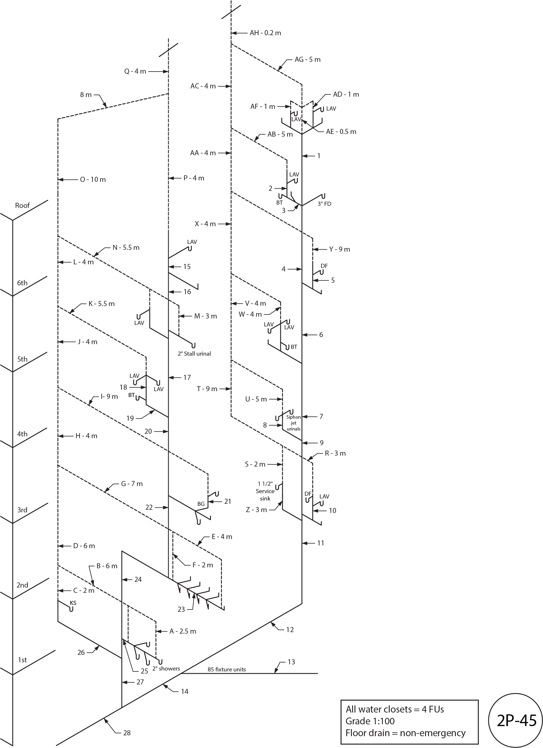 Figure 2P-45
- Using Figure 2P-45, fill in Table 15 by identifying and sizing the DWV drainage installation indicated by the numbers.
Table 15
| Number |
Name |
Hydraulic Load (FU) |
Size |
| 1 |
|
|
|
| 2 |
|
|
|
| 3 |
|
|
|
| 4 |
|
|
|
| 5 |
|
|
|
| 6 |
|
|
|
| 7 |
|
|
|
| 8 |
|
|
|
| 9 |
|
|
|
| 10 |
|
|
|
| 11 |
|
|
|
| 12 |
|
|
|
| 13 |
|
|
|
| 14 |
|
|
|
| 15 |
|
|
|
| 16 |
|
|
|
| 17 |
|
|
|
| 18 |
|
|
|
| 19 |
|
|
|
| 20 |
|
|
|
| 21 |
|
|
|
| 22 |
|
|
|
| 23 |
|
|
|
| 24 |
|
|
|
| 25 |
|
|
|
| 26 |
|
|
|
| 27 |
|
|
|
| 28 |
|
|
|
- Using Figure 2P-45, fill in Table 16 by identifying and sizing the DWV venting installation indicated by the letters.
Table 16
| Letter |
Name |
Hydraulic Load (FU) |
Length |
Size |
| A |
|
|
|
|
| B |
|
|
|
|
| C |
|
|
|
|
| D |
|
|
|
|
| E |
|
|
|
|
| F |
|
|
|
|
| G |
|
|
|
|
| H |
|
|
|
|
| I |
|
|
|
|
| J |
|
|
|
|
| K |
|
|
|
|
| L |
|
|
|
|
| M |
|
|
|
|
| N |
|
|
|
|
| O |
|
|
|
|
| P |
|
|
|
|
| Q |
|
|
|
|
| R |
|
|
|
|
| S |
|
|
|
|
| T |
|
|
|
|
| U |
|
|
|
|
| V |
|
|
|
|
| W |
|
|
|
|
| X |
|
|
|
|
| Y |
|
|
|
|
| Z |
|
|
|
|
| AA |
|
|
|
|
| AB |
|
|
|
|
| AC |
|
|
|
|
| AD |
|
|
|
|
| AE |
|
|
|
|
| AF |
|
|
|
|
| AG |
|
|
|
|
| AH |
|
|
|
|
Answer Key: Self-Test D-1.9 is on the next page.
