Self-Test D-1.8 Sizing Branch and Circuit Vents
Complete Self-Test D-1.8 and check your answers.
- Using Figure 2P-28, fill in Table 1 by identifying and sizing the circuit vent installation as per the NPC.
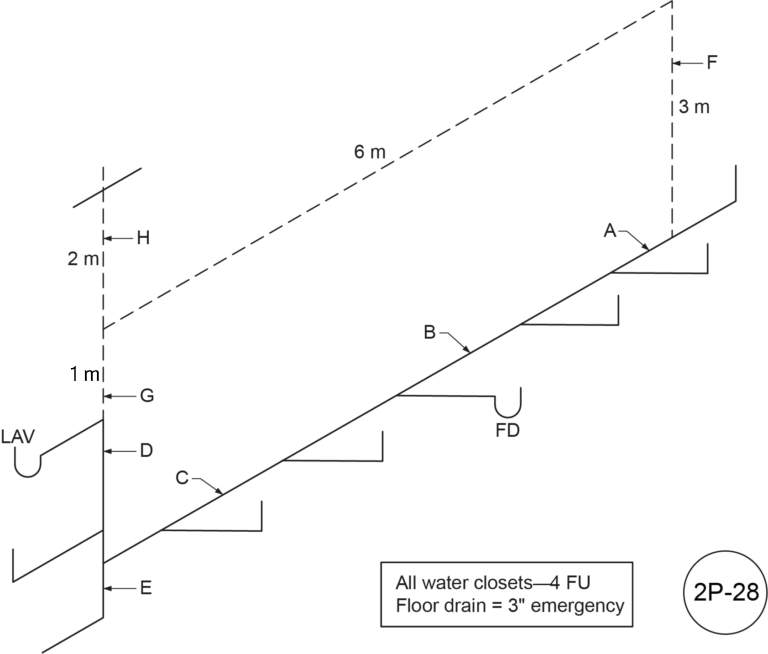 Figure 2P-28
Table 1
| Letter |
Name |
Hydraulic Load (FU) |
Length |
Size |
| A |
|
|
|
|
| B |
|
|
|
|
| C |
|
|
|
|
| D |
|
|
|
|
| E |
|
|
|
|
| F |
|
|
|
|
| G |
|
|
|
|
| H |
|
|
|
|
- Using Figure 2P-29, fill in Table 2 by identifying and sizing the circuit vent installation as per the NPC.
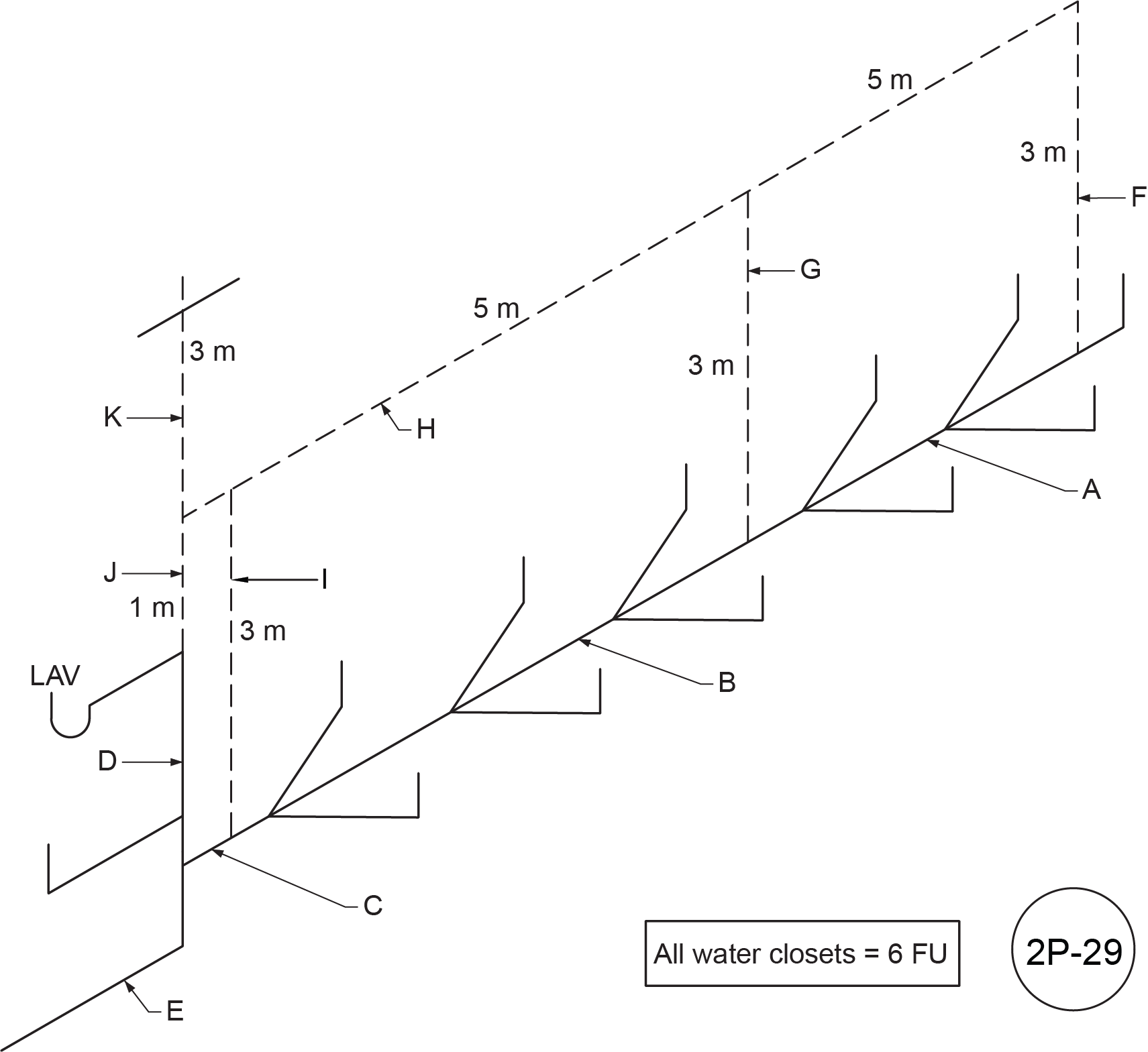 Figure 2P-29
Table 2
| Letter |
Name |
Hydraulic Load (FU) |
Length |
Size |
| A |
|
|
|
|
| B |
|
|
|
|
| C |
|
|
|
|
| D |
|
|
|
|
| E |
|
|
|
|
| F |
|
|
|
|
| G |
|
|
|
|
| H |
|
|
|
|
| I |
|
|
|
|
| J |
|
|
|
|
| K |
|
|
|
|
- Using Figure 2P-30, fill in Table 3 by identifying and sizing the circuit vent installation as per the NPC.
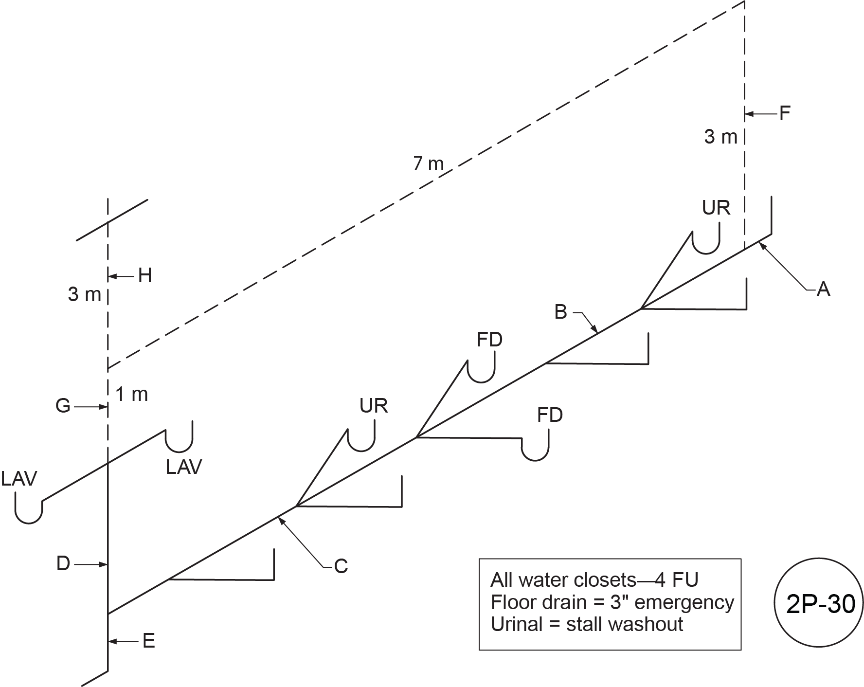 Figure 2P-30
Table 3
| Letter |
Name |
Hydraulic Load (FU) |
Length |
Size |
| A |
|
|
|
|
| B |
|
|
|
|
| C |
|
|
|
|
| D |
|
|
|
|
| E |
|
|
|
|
| F |
|
|
|
|
| G |
|
|
|
|
| H |
|
|
|
|
- Using Figure 2P-31, fill in Table 4 by identifying and sizing the circuit vent installation as per the NPC.
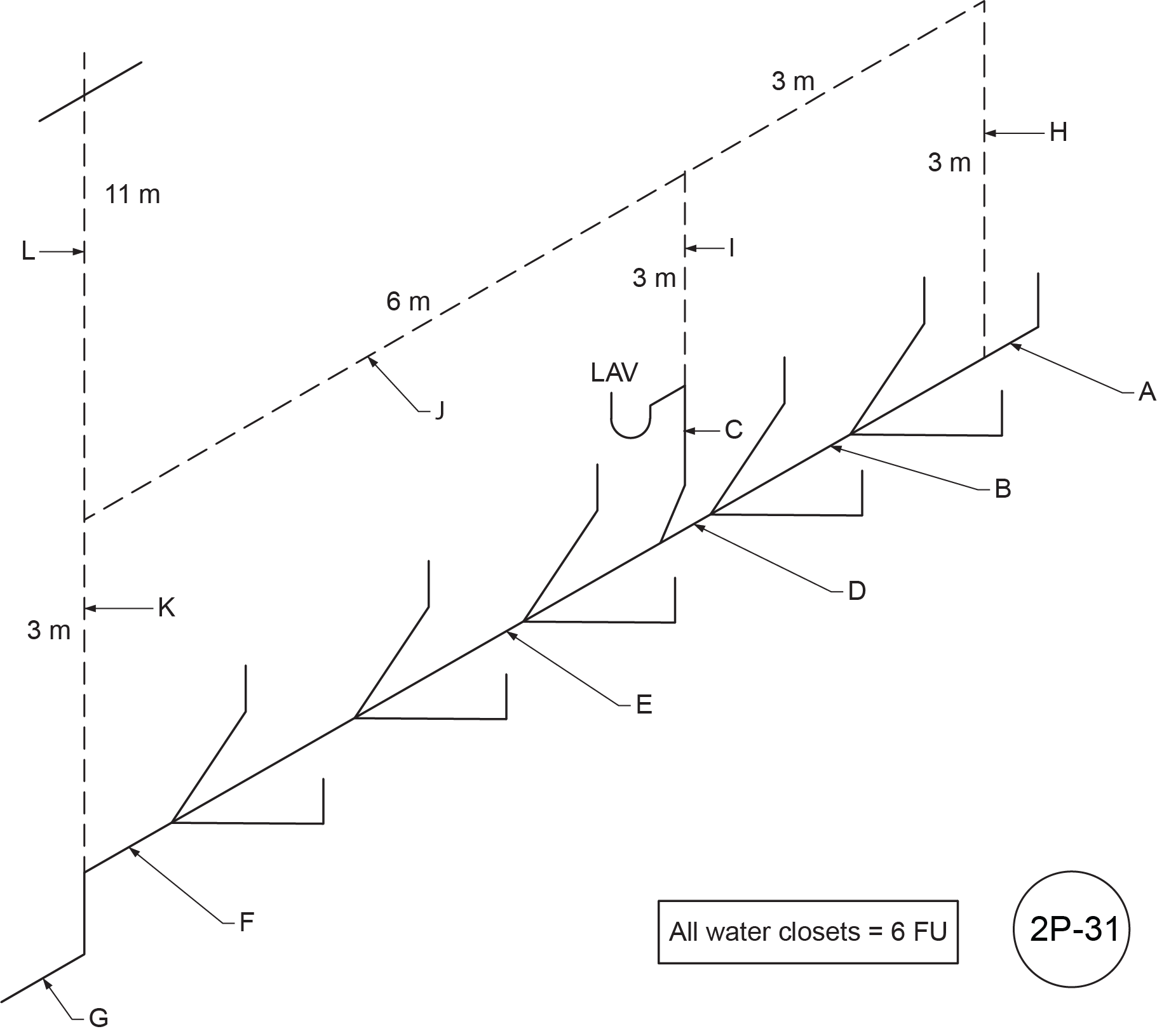 Figure 2P-31
Table 4
| Letter |
Name |
Hydraulic Load (FU) |
Length |
Size |
| A |
|
|
|
|
| B |
|
|
|
|
| C |
|
|
|
|
| D |
|
|
|
|
| E |
|
|
|
|
| F |
|
|
|
|
| G |
|
|
|
|
| H |
|
|
|
|
| I |
|
|
|
|
| J |
|
|
|
|
| K |
|
|
|
|
| L |
|
|
|
|
- Using Figure 2P-32, fill in Table 5 by identifying and sizing the circuit vent installation as per the NPC.
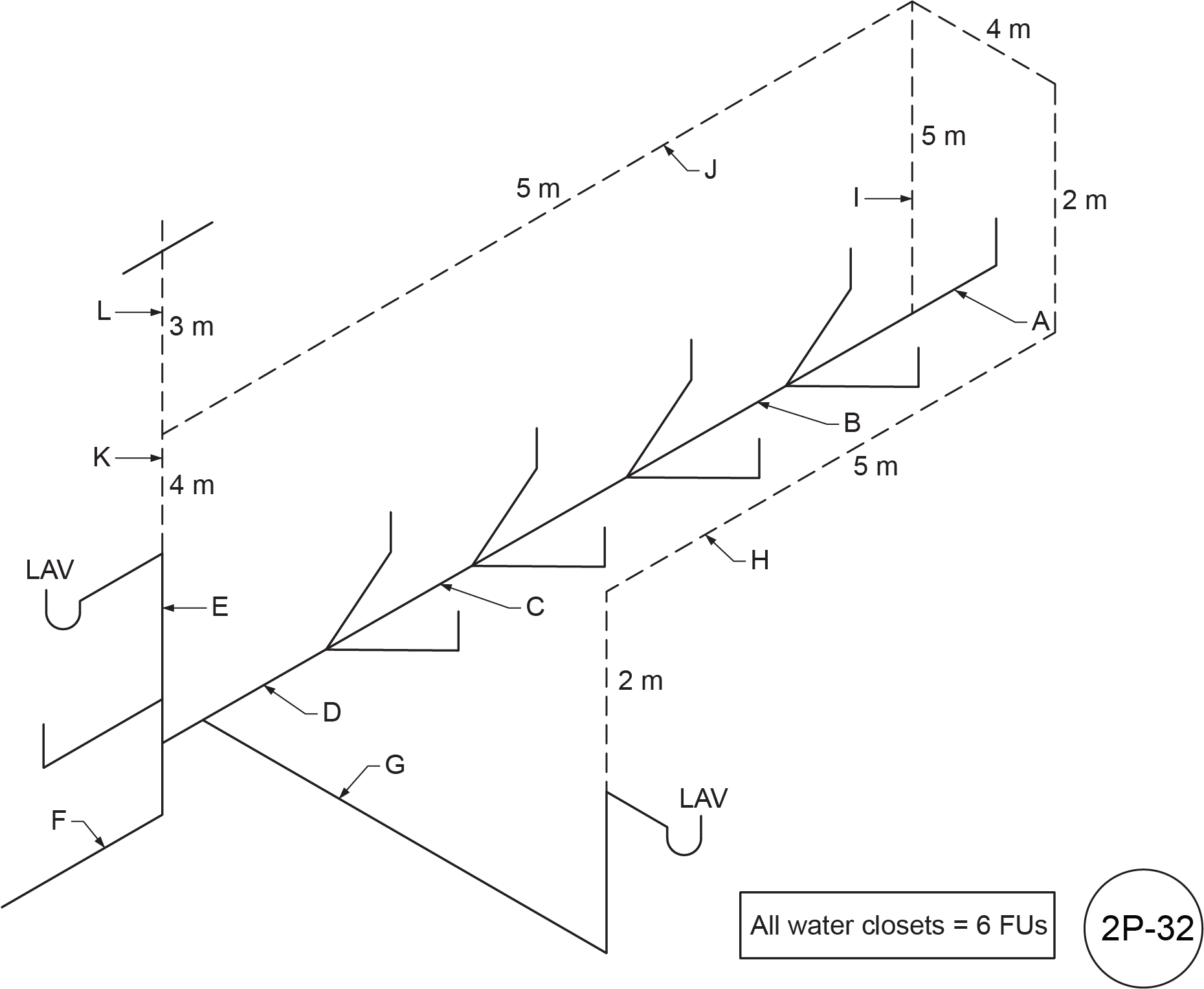 Figure 2P-32
Table 5
| Letter |
Name |
Hydraulic Load (FU) |
Length |
Size |
| A |
|
|
|
|
| B |
|
|
|
|
| C |
|
|
|
|
| D |
|
|
|
|
| E |
|
|
|
|
| F |
|
|
|
|
| G |
|
|
|
|
| H |
|
|
|
|
| I |
|
|
|
|
| J |
|
|
|
|
| K |
|
|
|
|
| L |
|
|
|
|
- Using Figure 2P-33, fill in Table 6 by identifying and sizing the circuit vent installation as per the NPC.
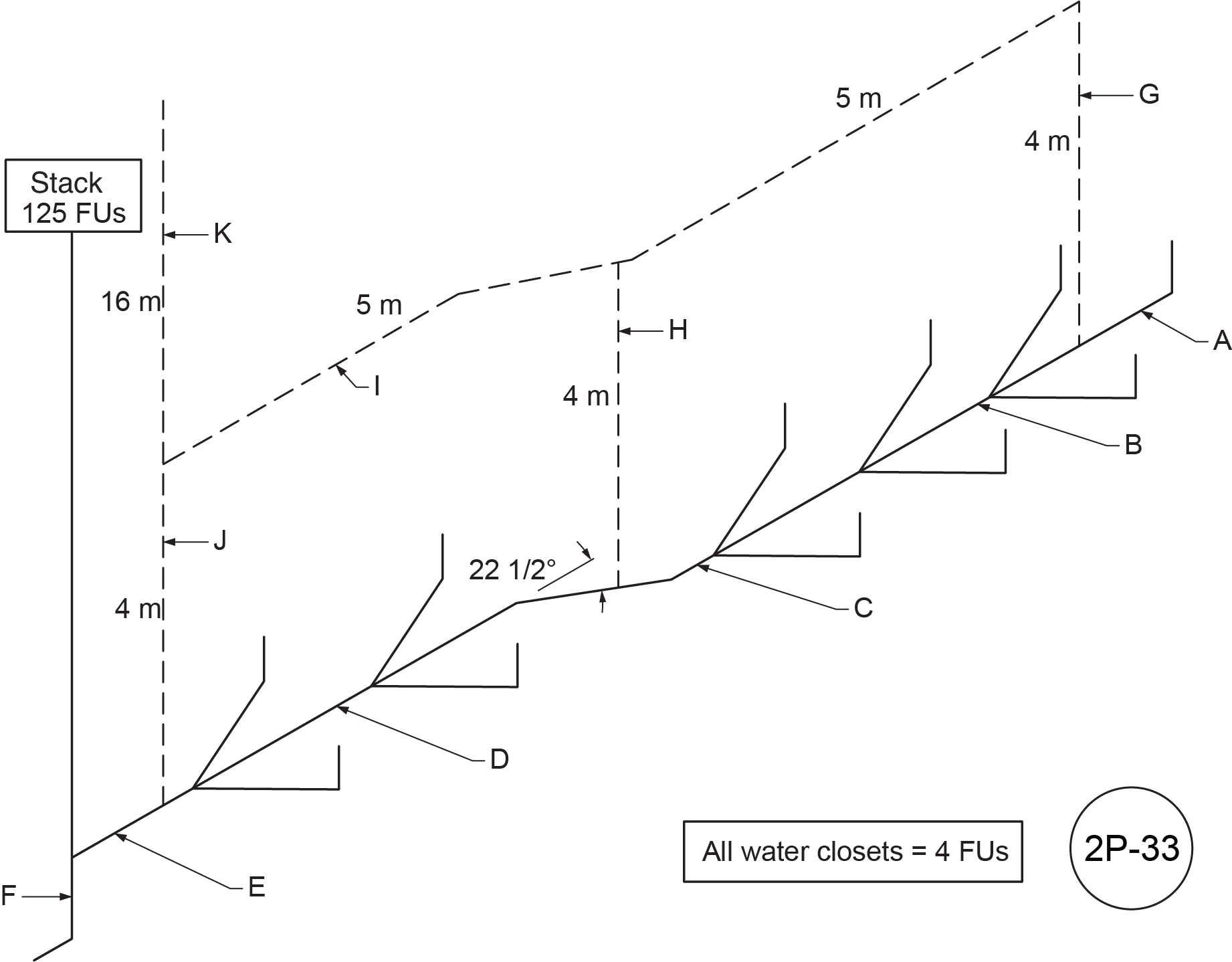 Figure 2P-33
Table 6
| Letter |
Name |
Hydraulic Load (FU) |
Length |
Size |
| A |
|
|
|
|
| B |
|
|
|
|
| C |
|
|
|
|
| D |
|
|
|
|
| E |
|
|
|
|
| F |
|
|
|
|
| G |
|
|
|
|
| H |
|
|
|
|
| I |
|
|
|
|
| J |
|
|
|
|
| K |
|
|
|
|
- Using Figure 2P-34, fill in Table 7 by identifying and sizing the circuit vent installation as per the NPC.
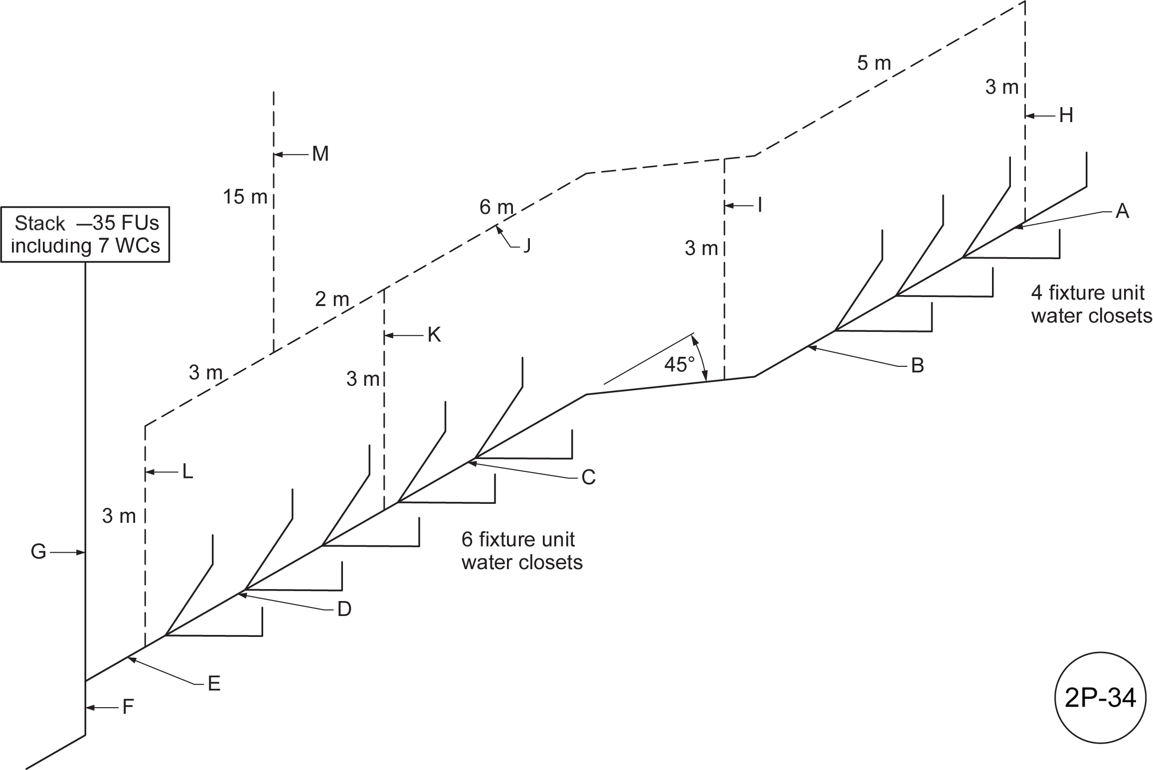 Figure 2P-34
Table 7
| Letter |
Name |
Hydraulic Load (FU) |
Length |
Size |
| A |
|
|
|
|
| B |
|
|
|
|
| C |
|
|
|
|
| D |
|
|
|
|
| E |
|
|
|
|
| F |
|
|
|
|
| G |
|
|
|
|
| H |
|
|
|
|
| I |
|
|
|
|
| J |
|
|
|
|
| K |
|
|
|
|
| L |
|
|
|
|
| M |
|
|
|
|
- Using Figure 2P-35, fill in Table 8 by identifying and sizing the circuit vent installation as per the NPC.
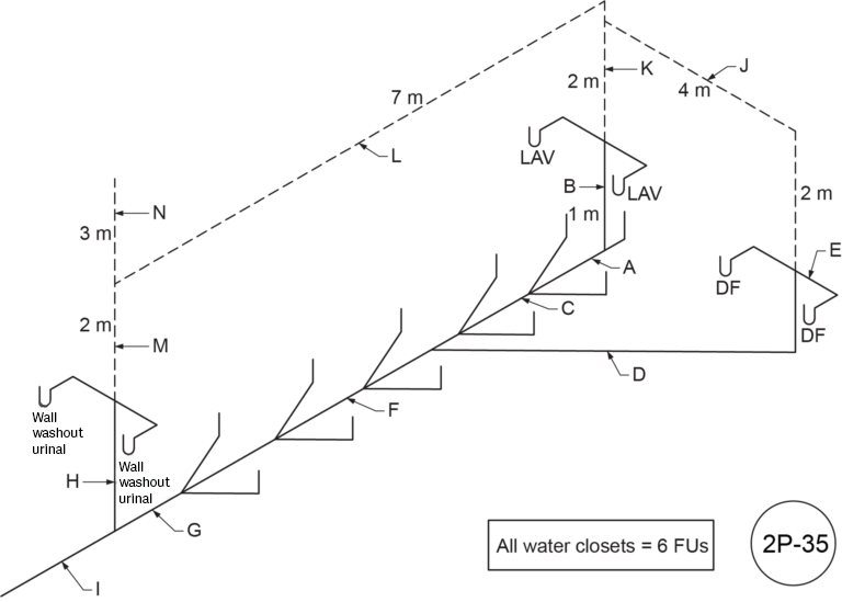 Figure 2P-35
Table 8
| Letter |
Name |
Hydraulic Load (FU) |
Length |
Size |
| A |
|
|
|
|
| B |
|
|
|
|
| C |
|
|
|
|
| D |
|
|
|
|
| E |
|
|
|
|
| F |
|
|
|
|
| G |
|
|
|
|
| H |
|
|
|
|
| I |
|
|
|
|
| J |
|
|
|
|
| K |
|
|
|
|
| L |
|
|
|
|
| M |
|
|
|
|
| N |
|
|
|
|
- Using Figure 2P-36, fill in Table 9 by identifying and sizing the circuit vent installation as per the NPC.
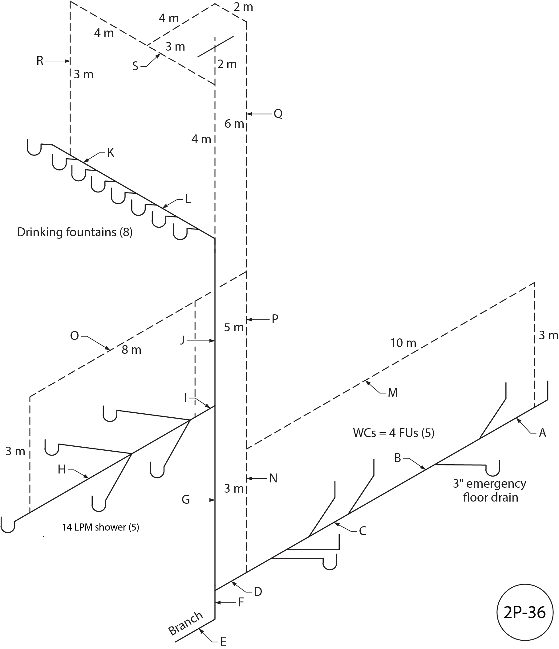 Figure 2P-36
Table 9
| Letter |
Name |
Hydraulic Load (FU) |
Length |
Size |
| A |
|
|
|
|
| B |
|
|
|
|
| C |
|
|
|
|
| D |
|
|
|
|
| E |
|
|
|
|
| F |
|
|
|
|
| G |
|
|
|
|
| H |
|
|
|
|
| I |
|
|
|
|
| J |
|
|
|
|
| K |
|
|
|
|
| L |
|
|
|
|
| M |
|
|
|
|
| N |
|
|
|
|
| O |
|
|
|
|
| P |
|
|
|
|
| Q |
|
|
|
|
| R |
|
|
|
|
| S |
|
|
|
|
- Using Figure 2P-37, fill in Table 10 by identifying and sizing the circuit vent installation as per the NPC.
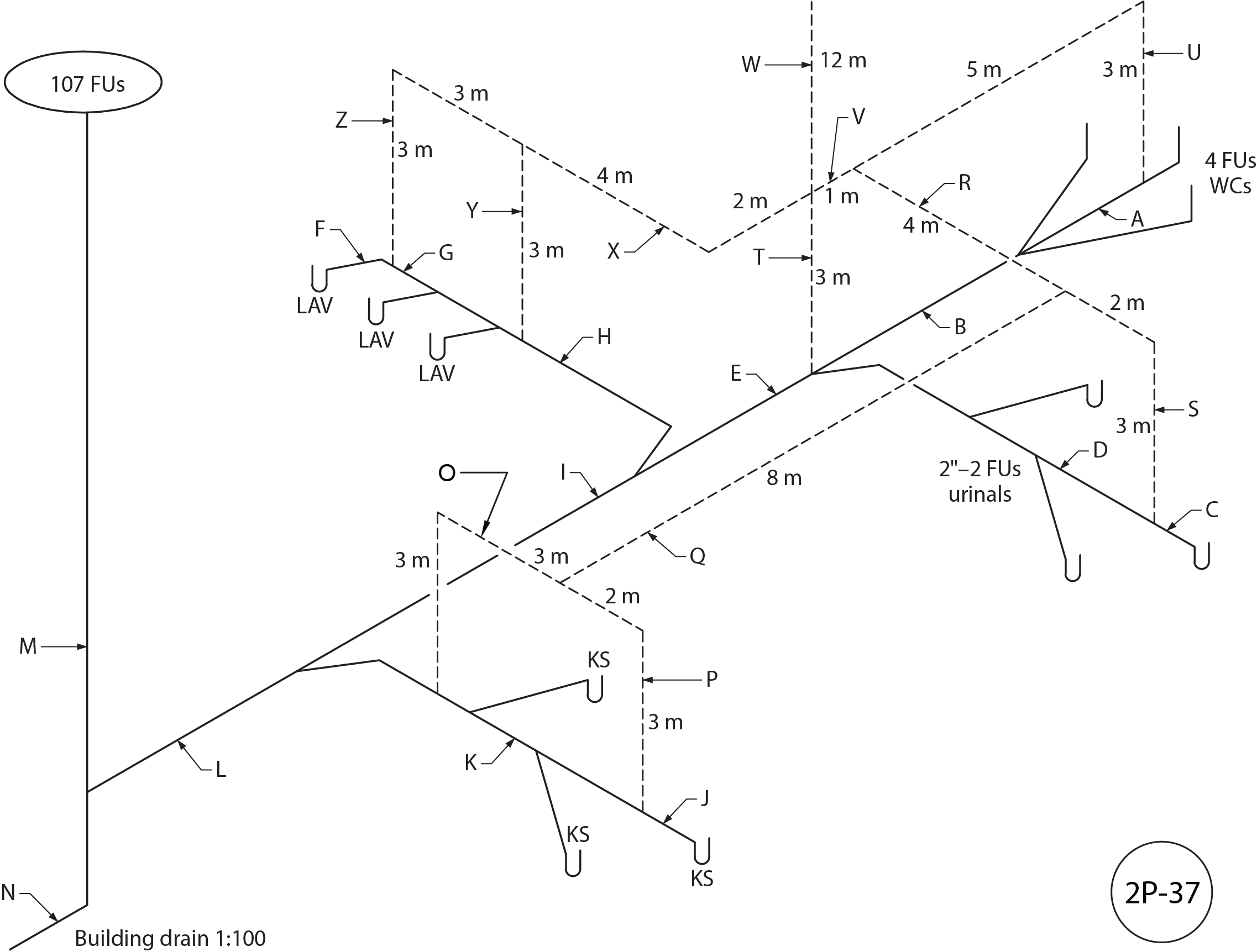 Figure 2P-37
Table 10
| Letter |
Name |
Hydraulic Load (FU) |
Length |
Size |
| A |
|
|
|
|
| B |
|
|
|
|
| C |
|
|
|
|
| D |
|
|
|
|
| E |
|
|
|
|
| F |
|
|
|
|
| G |
|
|
|
|
| H |
|
|
|
|
| I |
|
|
|
|
| J |
|
|
|
|
| K |
|
|
|
|
| L |
|
|
|
|
| M |
|
|
|
|
| N |
|
|
|
|
| O |
|
|
|
|
| P |
|
|
|
|
| Q |
|
|
|
|
| R |
|
|
|
|
| S |
|
|
|
|
| T |
|
|
|
|
| U |
|
|
|
|
| V |
|
|
|
|
| W |
|
|
|
|
| X |
|
|
|
|
| Y |
|
|
|
|
| Z |
|
|
|
|
Answer Key: Self-Test D-1.8 is on the next page.
